Installation Manual - Carbon SLT Gateway
This manual guides the designer or installer through the specification and installation of the electrical connections of the Carbon communication gateway for SLT systems (Tag Reading System).
Power Supply
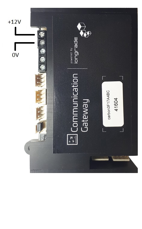
Power must be supplied at 12 VDC ±5%, as indicated on the equipment. Consumption is 120 mA.
| Specification | Value |
|---|---|
| Supply voltage | 12 VDC ±5% |
| Consumption | 120 mA |
Use a regulated power supply sized to support the gateway and the load connected to the status relay.
Ethernet RJ45 Connection
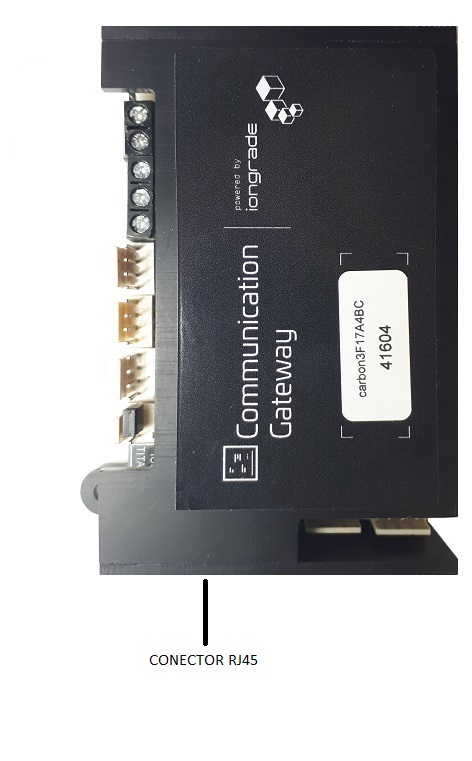
For communication through Ethernet RJ45 media, use the connector located on the device. The Ethernet interface (10/100-Base-T) is one of the media through which the gateway establishes the TCP/IP connection with the SLT server, and it can also forward the data to the access controller via UDP socket.
Besides Ethernet RJ45, the gateway can use the WiFi network to communicate. The media choice (WiFi or Ethernet) is made in the gateway configuration, through a web browser.
Wiegand or Abatrack Output Connection
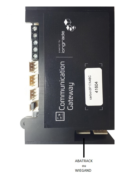
To transmit the received data to the access controller through the Wiegand or Abatrack interface, use the connector identified on the equipment.
To use this interface, a cable with the connector is supplied with the equipment, and each wire is identified by its color and by a label.
The transmission protocol (for example, Abatrack Standard) is defined in the gateway configuration. The chosen protocol must be able to carry the tag identification (OBUID) — some protocols have value limitations and cannot hold the tag values.
RS232 Serial Output Connection
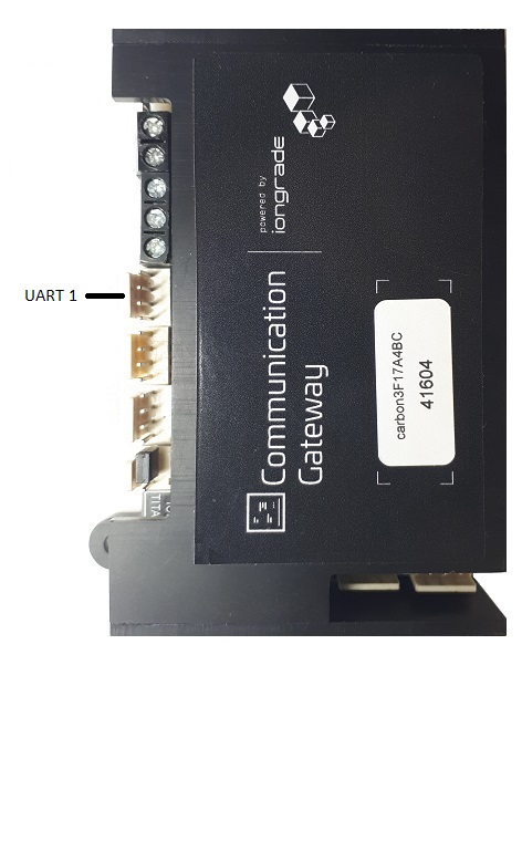
To transmit the received data to the access controller through the RS232 serial interface, use the UART1 connector identified on the equipment.
To use this interface, a cable with the connector is supplied with the equipment, and each wire is identified by a label.
The transmission protocol of the serial output (DATA<CR>) is defined in the gateway configuration, where you can also state that this interface will be inactive.
Status Relay
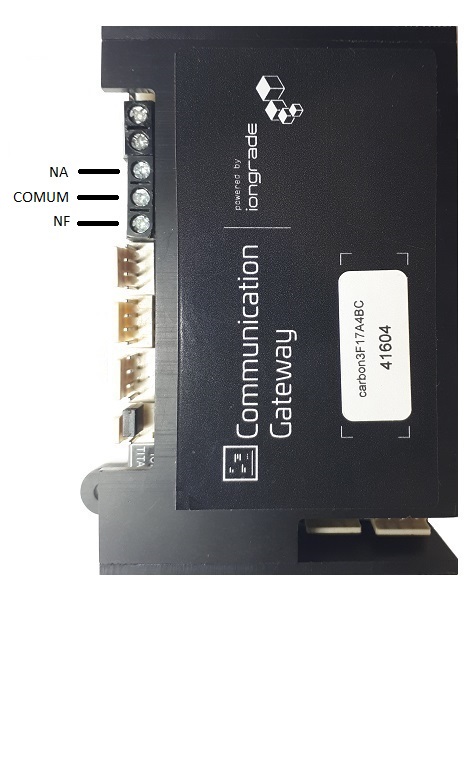
The state of the TCP connection with the SLT server is signaled through a relay. The relay contacts (NO / COMMON / NC) are identified on the equipment.
When the connection with the SLT server is active, the status relay is energized.
| Contact | Description |
|---|---|
| NO | Normally open contact |
| COMMON | Common contact |
| NC | Normally closed contact |
Message Display
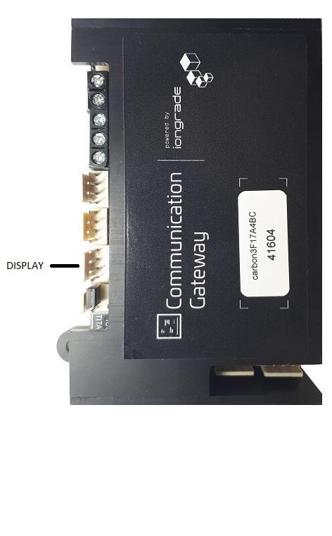
In situations where it is necessary to view the state of the Carbon gateway's communication with the SLT server, an optional display (LCD) can be used.
The display shows the date/time and the state of the communication with the Ethernet or WiFi network, with the SLT server and with the MQTT broker, if one is being used.
RESET and MODE Buttons and STATUS LED
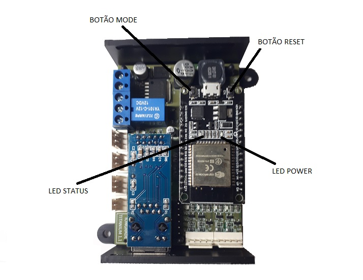
The gateway has two buttons that allow you to force a reset (boot) or switch it into configuration mode. It also has a STATUS LED that shows the state of the equipment.
| Button | Function |
|---|---|
| RESET | Forces the reset (boot). Press it quickly to exit configuration mode. |
| MODE | Switches the gateway into configuration mode. Press and hold for 6 seconds. |
Reading the STATUS LED
When the gateway is in operation mode, the STATUS LED provides information about the general state of the communication. Every two seconds a series of up to four quick blinks starts. When four blinks are counted in each cycle, the situation is normal. In the blink series, the meaning of each one is as follows:
| Blink | Meaning |
|---|---|
| 1 | The gateway is in operation mode |
| 2 | Connection with the network (Ethernet or WiFi) is OK |
| 3 | Connection with the MQTT broker is OK |
| 4 | Communication with the system server is OK |
Blinks number 3 and 4 should only be considered when the gateway is operating connected to a broker through the MQTT connection.
When the gateway is in configuration mode, the STATUS LED blinks quickly and continuously, indicating that configuration mode is active.
Checking these conditions through the STATUS LED helps a lot during the installation and maintenance of the equipment, to locate communication failures.
Accessing the Configuration
The Carbon gateway is configured through a browser. To start the configuration, follow the steps below:
- Switch the gateway into configuration mode — press and hold the MODE button for 6 seconds. The gateway restarts automatically in configuration mode and activates a WiFi access point (AP mode).
- Connect to the gateway's WiFi network — the access point has a unique SSID, formed by the word
carbonfollowed by an identification code of the gateway (e.g.,carbon7512208F,carbon89C0CF6A). - Point the browser to the gateway — go to the address
192.168.4.1.
The gateway will ask for a username and password to start the session. The default values are:
| Field | Default value |
|---|---|
| Usuário (Username) | admin |
| Senha (Password) | carbonpwd |
To force the reset and exit configuration mode, simply press the RESET button quickly.
Next Steps
- Overview — SLT system architecture, support for multiple lanes and specifications