Installation Manual - Cobalt
This manual guides the designer or installer through the specification and physical installation of the COBALT module, including the power supply, the connection terminal block, and the definition of the board role (Main or Subordinate).
Cobalt Module Connections
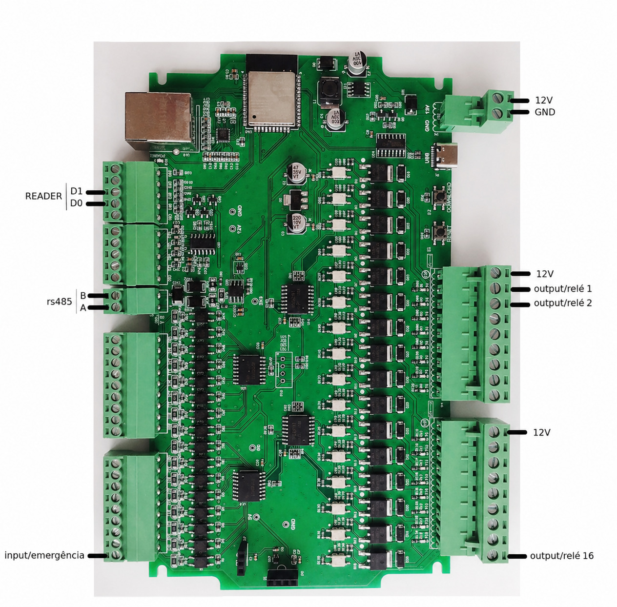
The table below describes the connections of the COBALT-QD32 terminal block, as identified on the board.
| Connection | Terminals / Signals | Function |
|---|---|---|
| Power supply | 12V, GND | Module power supply from an external 12 Vdc source |
| READER | D0, D1 | Connection of an access control reader using the Wiegand protocol |
| Input/Emergency | input/emergência | Signal input active on low logic level |
| Digital outputs | output/relé 1 … output/relé 16 | 16 outputs that supply 12 Vdc to drive external relays |
| RS485 | A, B | Expansion bus for connecting up to 3 additional modules |
Power Supply
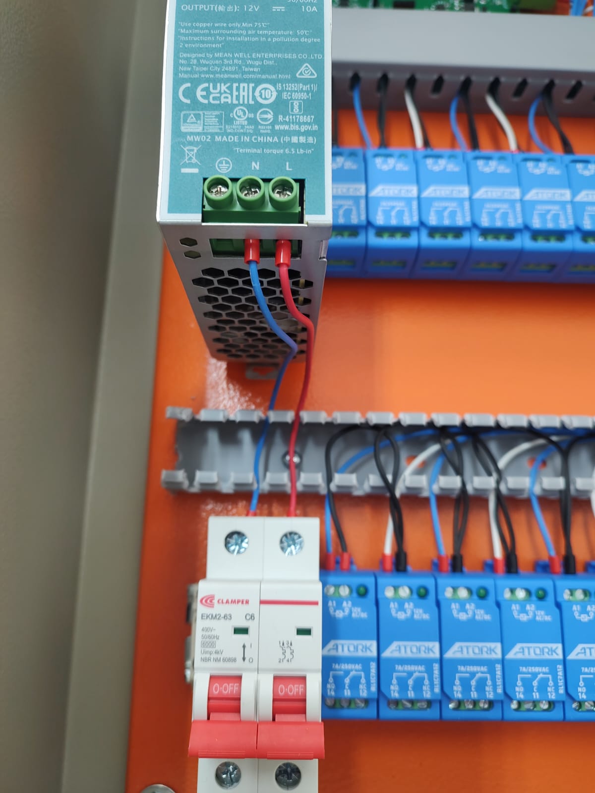
The Cobalt module is powered by an external 12 Vdc power supply, connected to the 12V and GND terminals.
| Specification | Value |
|---|---|
| Supply voltage | 12 Vdc (external power supply) |
Use a power supply sized to support the module and the set of external relays driven by the digital outputs.
Reader Connection (READER)
The READER interface is intended for connecting access control readers using the Wiegand protocol, through the D0 and D1 signals.
| Terminal | Signal |
|---|---|
D0 | Wiegand data 0 |
D1 | Wiegand data 1 |
Input/Emergency Input
The Input/Emergency input is active on low logic level and is intended for use in emergency situations, allowing all elevator buttons to be released.
Digital Outputs and External Relays
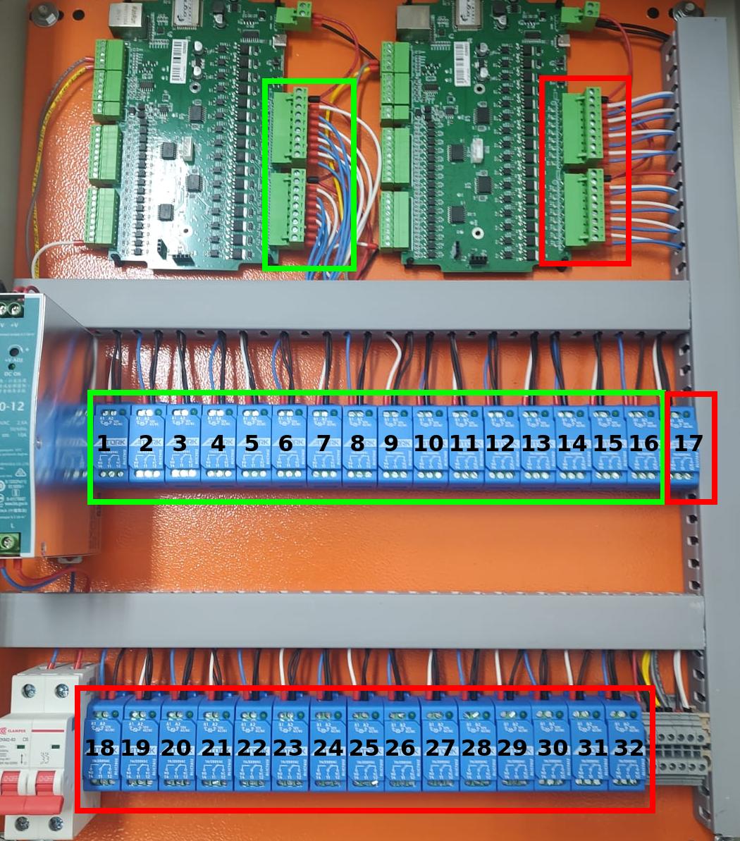
The 16 digital outputs supply 12 Vdc to drive the external relays responsible for the electrical switching of the elevator button circuits.
| Terminal | Function |
|---|---|
12V (output block) | 12 Vdc reference for driving the relays |
output/relé 1 | Drives external relay 1 |
output/relé 2 | Drives external relay 2 |
| … | … |
output/relé 16 | Drives external relay 16 |
RS485 Connection (Expansion)
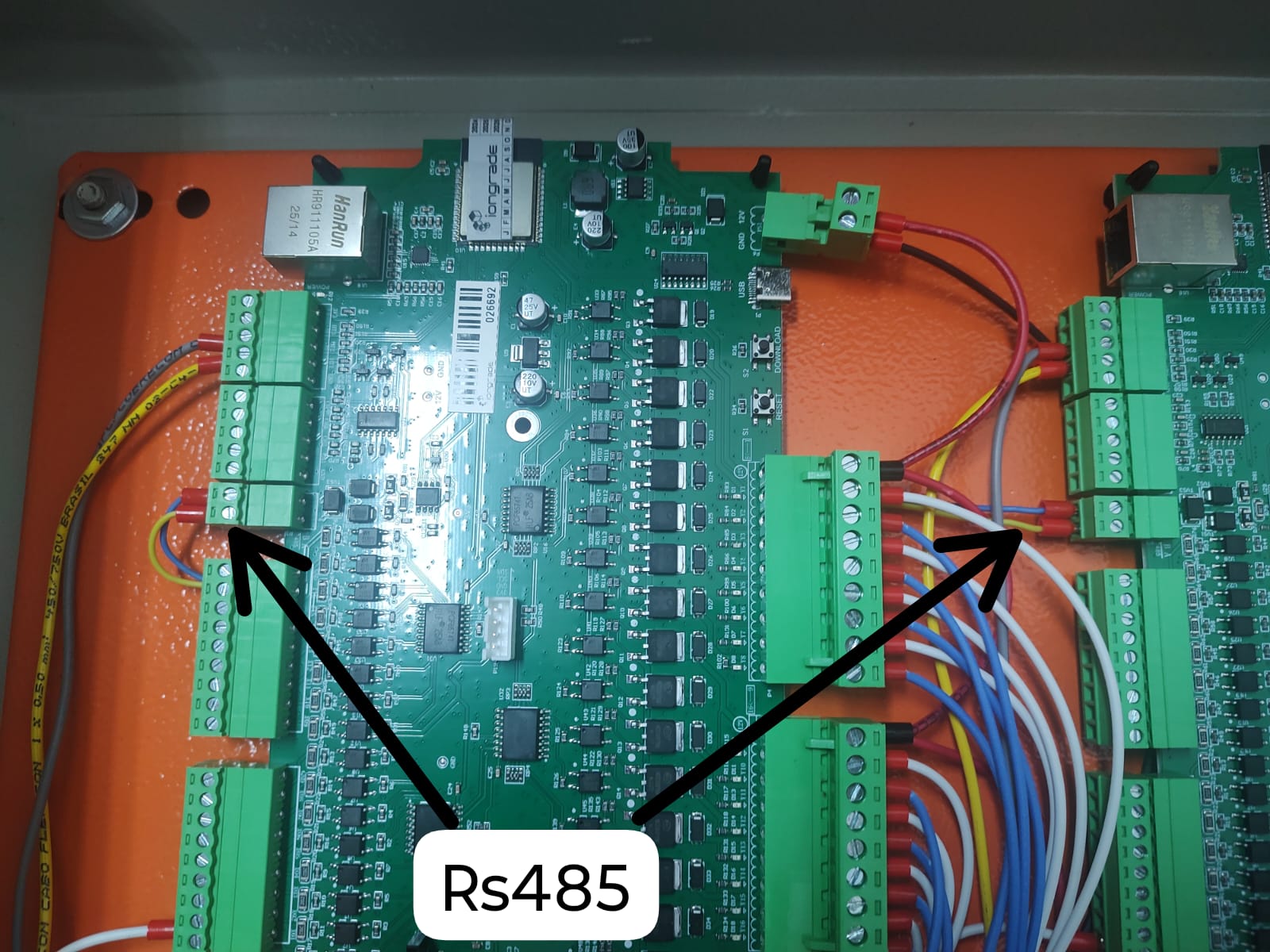
The RS485 interface is intended for connecting up to 3 additional modules over the bus, allowing the system to be expanded to up to 64 digital outputs.
| Terminal | Signal |
|---|---|
A | RS485 - A |
B | RS485 - B |
Buttons and Reset
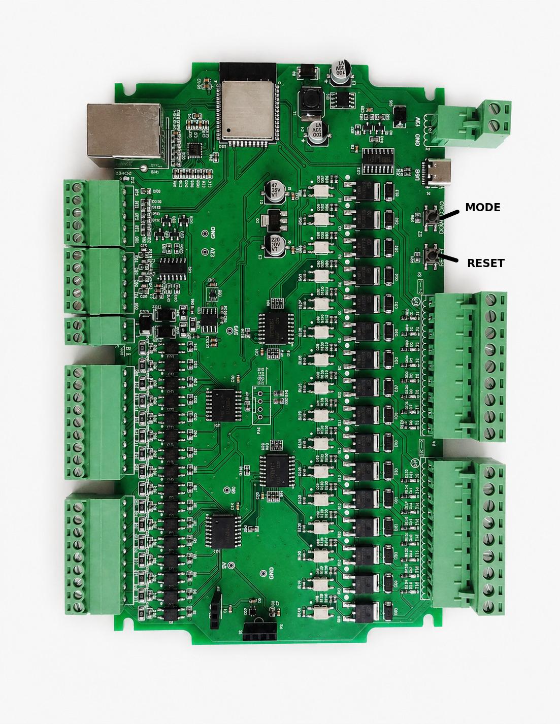
When powered on, the module enters normal operation. The module has two buttons:
| Button | Function |
|---|---|
| Download/Mode | Puts the module into configuration mode. Press and hold for eight seconds. |
| RESET | Restarts (reboots) the module. |
Defining the Board Role: Main or Subordinate
The role of each board is defined by the communication media chosen in the configuration:
| Configuration | Role | Connection used |
|---|---|---|
| Wi-Fi or Ethernet | Main | Communicates with the Accelero system and manages the Subordinate boards |
| RS485 | Subordinate | Expansion unit, controlled by the Main board over RS485 |
On a Subordinate board, the only configuration required is to enable RS485 communication and set the device ID. All other settings — network parameters, readers, floors, and system adjustments — must be made exclusively on the Main board.
Accessing the Configuration
The COBALT module is configured through a web browser. To start the configuration:
-
Activate configuration mode: power on the module, wait for normal operation, and press the Download/Mode button, holding it for eight seconds. The module restarts in configuration mode.
-
Wait about 30 seconds and check whether a new Wi-Fi network appeared, named
cobaltfollowed by the serial number (e.g.,cobalt012345). -
Connect to the module's Wi-Fi network. The SSID is unique and exclusive to each module.
-
Open the browser at
http://192.168.4.1and enter the default credentials:- Username:
admin - Password:
cobaltpwd
- Username:
Operating the Cobalt module requires the Accelero platform version 2.16.9-HF3 or higher.
Next Steps
- Overview — architecture, QD family, and technical specifications