Installation Manual - Iodine Converter
The Iodine has been discontinued and is no longer sold for new projects. This documentation remains available to support existing installations. For new projects or replacements, contact the Iongrade sales team.
This manual guides the designer or installer through the physical installation and the electrical connections of the Iodine protocol converter.
Power Supply
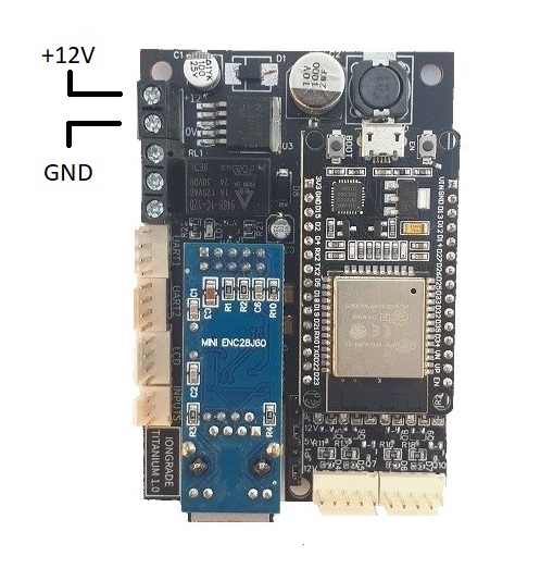
The converter must be powered with 12 VDC ±5%. Consumption, without readers and additional modules, is 120 mA.
| Specification | Value |
|---|---|
| Supply voltage | 12 VDC ±5% |
| Consumption (without peripherals) | 120 mA |
Use a regulated power supply rated to support the converter and all connected devices.
Wiegand/Abatrack Connections
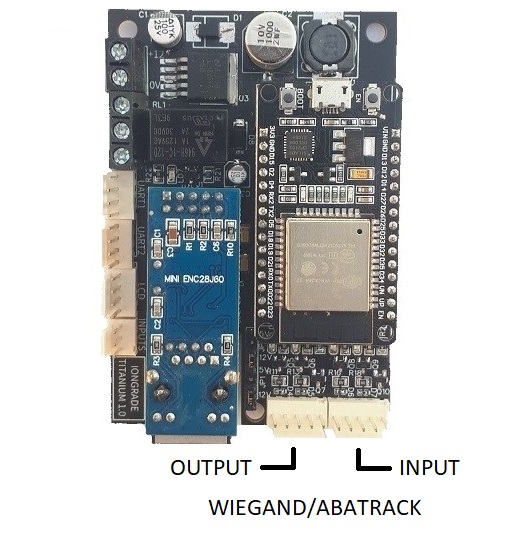
The board identifies the connectors where the input devices (readers) and output devices (controllers) of the Wiegand/Abatrack data channel must be wired. The electrical level of this interface is open collector.
Device Voltage Selection
There are two jumpers for selecting the supply voltage of the devices, with 5VDC or 12VDC options.
| Jumper | Function | Options |
|---|---|---|
| JP1 | Voltage selection for the output device | 5VDC or 12VDC |
| JP2 | Voltage selection for the input device | 5VDC or 12VDC |
The printed circuit board identifies, next to each jumper, the positions of each voltage option (12V or 5V).
UART Connections
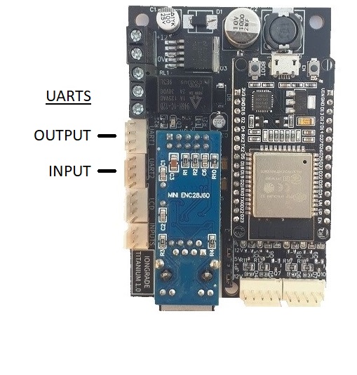
The board identifies the connectors where the input and output devices of the UART data channel must be wired. The electrical standard of the interfaces is RS232 and the converter supplies 5VDC limited to 300 mA per interface.
Serial Connector Pinout (UART1 and UART2)
| Pin | Signal |
|---|---|
| 1 | +5 VDC |
| 2 | TX |
| 3 | RX |
| 4 | GND |
Buttons and LEDs
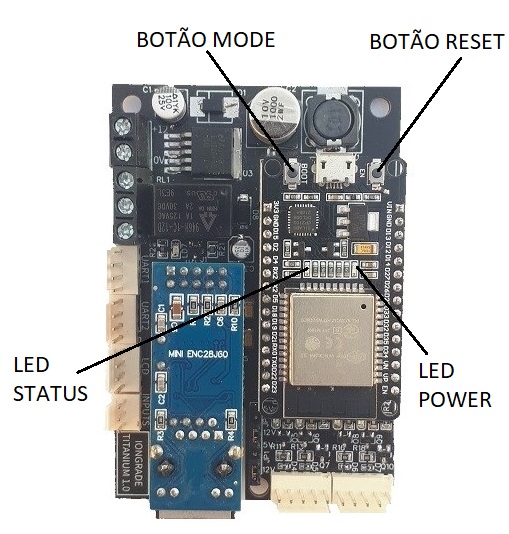
The converter has two buttons that allow you to force a reset (boot) or put it into configuration mode, and it has POWER and STATUS indicator lights.
MODE button — puts the converter into configuration mode. Press and hold it for a few seconds.
RESET button — forces the restart (boot). Press it briefly to exit configuration mode.
POWER LED — indicates that the equipment is powered.
STATUS LED — reports the general state of the equipment.
Reading the STATUS LED
When the converter is in operation mode, the STATUS LED provides information about the general state of the equipment. Every two seconds a series of up to two quick blinks starts. When two blinks are counted in each cycle, the situation is normal.
| Blink | Meaning |
|---|---|
| 1 | Converter in operation mode |
| 2 | Network connection (Ethernet or WiFi) OK |
Checking these conditions through the STATUS LED helps a lot during installation and maintenance, to locate communication failures.
Starting the Configuration
The Iodine converter is configured through a browser. To start the configuration, follow the steps below.
1. Activate Configuration Mode
- Press and hold the MODE button for a few seconds.
- The converter enters configuration mode, keeping the STATUS LED blinking quickly.
- A WiFi Access Point (AP) is activated, allowing external connections (a tablet or mobile phone, for example).
At the end of the configuration session, briefly press the RESET button; the equipment returns to normal operation and the Access Point is deactivated.
2. Connect to the Converter's WiFi Network
The WiFi network point created by the Iodine has a unique and exclusive name (SSID) for each converter, formed by the word iodine followed by a device identification code:
- Format:
iodine+ identification code - Examples:
iodineF67A,iodineF7A4
3. Access the Configuration Interface
-
Connect to the converter's WiFi network.
-
Open the browser and go to:
http://192.168.4.1 -
Enter the default credentials:
- User:
admin - Password:
iodinepwd
- User:
Installation Recommendations
- Location: install the converter in a place protected from the weather.
- Ventilation: ensure adequate ventilation for heat dissipation.
- Grounding: connect the grounding system properly.
- Cabling: use shielded cables for the readers in environments with interference.
- Protection: consider using surge protectors on the power supply.