Operation and Configuration Manual - Iodine Converter
The Iodine has been discontinued and is no longer sold for new projects. This documentation remains available to support existing installations. For new projects or replacements, contact the Iongrade sales team.
The Iodine protocol converter has an internal HTTP server, through which all operational settings, network parameters and system adjustments are made, accessible through a web browser. This manual describes each screen of the configuration interface of version v2.2 (firmware 2.0.7).
To access the configuration you must put the converter into Configuration mode (press and hold the MODE button for 6 seconds), connect to the Wi-Fi network it generates (SSID iodine followed by a device identification code, e.g.: iodineF67A, iodineF7A4) and point the browser to 192.168.4.1. The step by step is in the Installation Manual.
The Iodine receives data on up to three input channels and retransmits it on up to three output channels: Wiegand/Abatrack, UART (RS232 serial) and UDP Socket (network). Each channel is configured separately and all of them can operate simultaneously. So, for example, data received by a reader in Wiegand 26 can be transmitted in Abatrack, through the output UART and over UDP, all at the same time.
Login
When you connect the browser to the converter, a user name and password will be requested. The default values are:
- User:
admin - Password:
iodinepwd
Main Menu
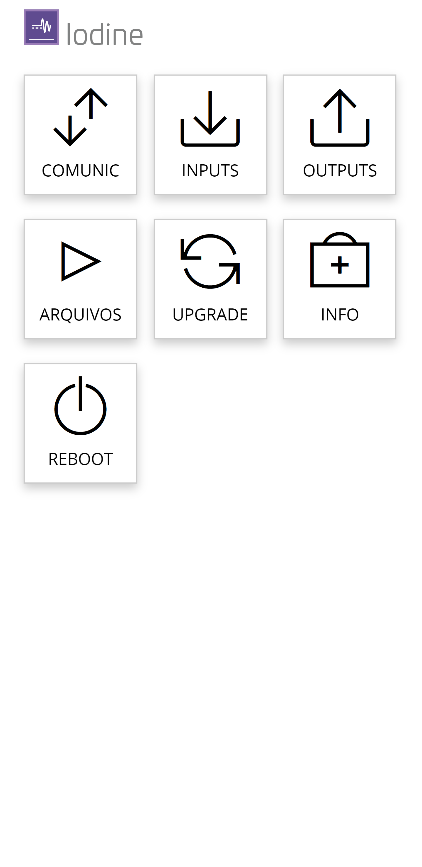
The initial configuration screen presents the following options:
- Comunic (Communication) — configuration of the Iodine's network communication.
- Inputs — configuration of the data input interfaces.
- Outputs — configuration of the data output interfaces.
- Arquivos (Files) — file functions (backup/restore/upload).
- Upgrade — access to the firmware update screen.
- Info — access to general information about the equipment.
- Reboot — restarts the equipment.
Communication
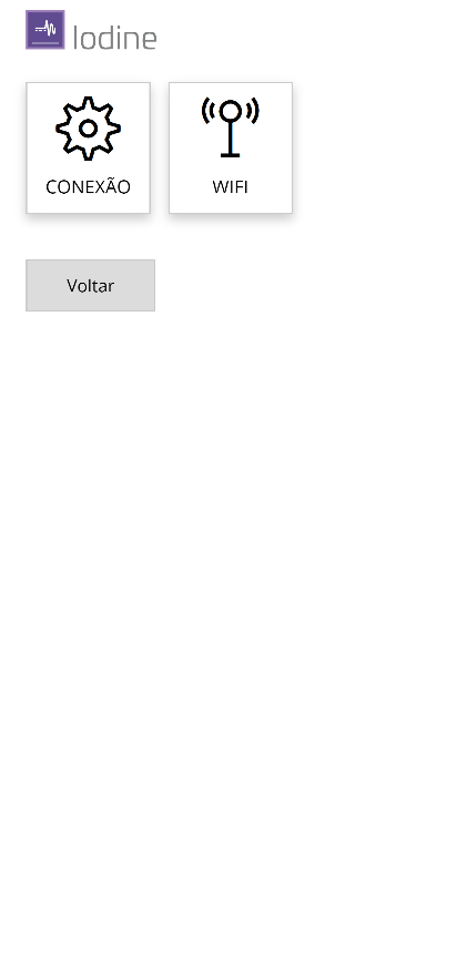
The Comunic menu gives access to the following screens:
- Conexão (Connection) — defines the type of media used to connect the converter to the communication network when it is in operation.
- WiFi — Wi-Fi network parameters, in case the equipment will use a wireless connection.
Connection
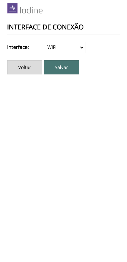
On this screen you define the type of media the converter will use to connect to the communication network when it is in operation mode. The options are:
- Rede inativa (network disabled)
- WiFi (Wireless)
Make the necessary changes and click Salvar (Save) to confirm.
WiFi
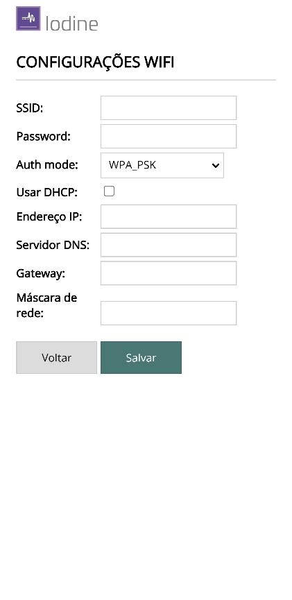
Use this screen to enter the data and access parameters of the Wi-Fi network that will be used in operation mode.
Make the necessary changes and click Salvar to confirm.
Inputs
There are three data input interfaces on the equipment. On this screen, choose the input interface to configure:
- WIE-ABA — data input from badge readers in the Wiegand or Abatrack formats.
- UART — data input through an RS232 serial port.
- UDP SOCK — data input through a network connection using the UDP protocol.
The TESTES (Tests) option lets you monitor the data reception on each interface.
Wiegand-Abatrack Input
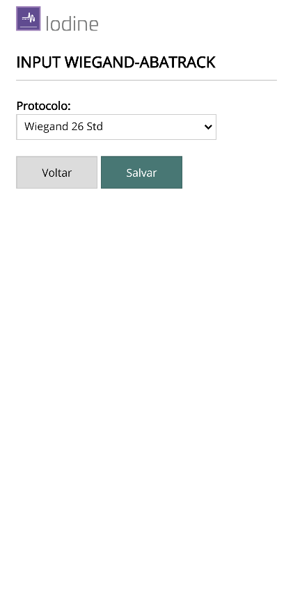
Use this screen to specify the protocol of the data to be received on the Wiegand/Abatrack interface.
| Field | Description |
|---|---|
| Protocolo (Protocol) | Format of the data received on the interface. The Wiegand/Abatrack interfaces can operate in several formats (Wiegand 26, 32, 34, etc.). |
Make the necessary changes and click Salvar to confirm.
UART Input
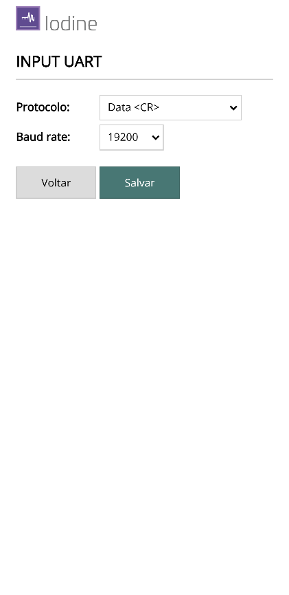
Use this screen to specify the protocol and the communication speed (baud rate) of the UART input interface.
| Field | Description |
|---|---|
| Protocolo | Protocol of the data received on the serial interface. The converter is prepared to handle custom encrypted codes. |
| Baud rate | Serial communication speed of the input interface. |
Make the necessary changes and click Salvar to confirm.
UDP Input
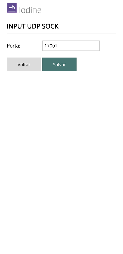
Use this screen to specify the UDP port number through which the data of the UDP SOCK interface will be received.
| Field | Description |
|---|---|
| Porta (Port) | UDP port number for receiving the data. To disable the interface, set the port to 0 (zero). |
Make the necessary changes and click Salvar to confirm.
Tests
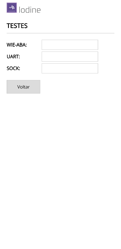
Use this screen to monitor the data input on the equipment's interfaces. The received data is displayed on the screen itself, which helps a lot to validate the wiring during installation and maintenance.
Outputs
There are three data output interfaces on the equipment. On this screen, choose the interface to configure:
- WIE-ABA — data output in the Wiegand or Abatrack formats.
- UART — data output through an RS232 serial port.
- UDP SOCK — data output through a network connection using the UDP protocol.
Wiegand-Abatrack Output
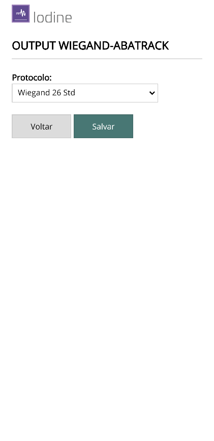
Use this screen to specify the protocol of the data to be transmitted on the Wiegand/Abatrack interface.
| Field | Description |
|---|---|
| Protocolo | Format of the data transmitted on the interface (Wiegand 26, 32, 34, etc.). |
Make the necessary changes and click Salvar to confirm.
UART Output
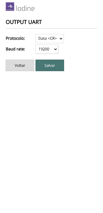
Use this screen to specify the protocol and the communication speed (baud rate) of the UART data output interface.
| Field | Description |
|---|---|
| Protocolo | Protocol of the data transmitted on the serial interface. |
| Baud rate | Serial communication speed of the output interface. |
Make the necessary changes and click Salvar to confirm.
UDP Output
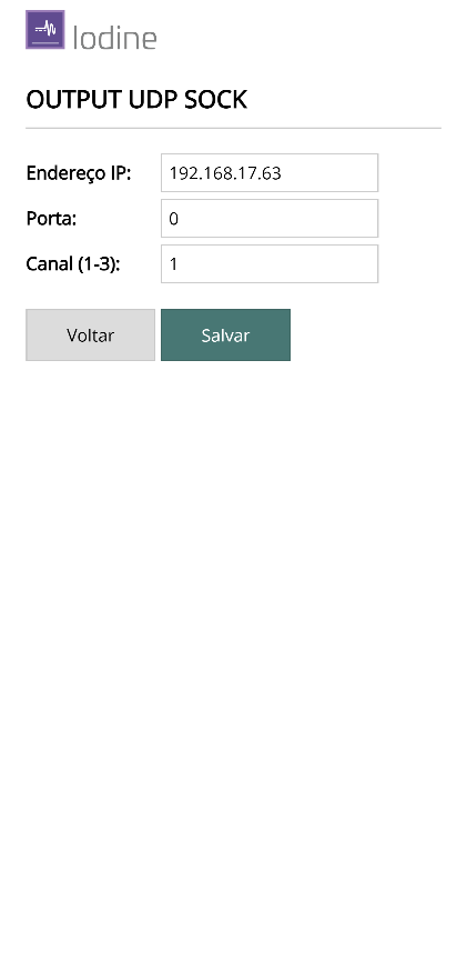
Use this screen to specify the UDP port number through which the data of the UDP SOCK interface will be transmitted.
| Field | Description |
|---|---|
| Porta | UDP port number for transmitting the data. To disable the interface, set the port to 0 (zero). |
| Canal (Channel) | When the data is sent to an Aurum controller, the channel number corresponds to one of the controller's three reader inputs. |
Make the necessary changes and click Salvar to confirm.
Files
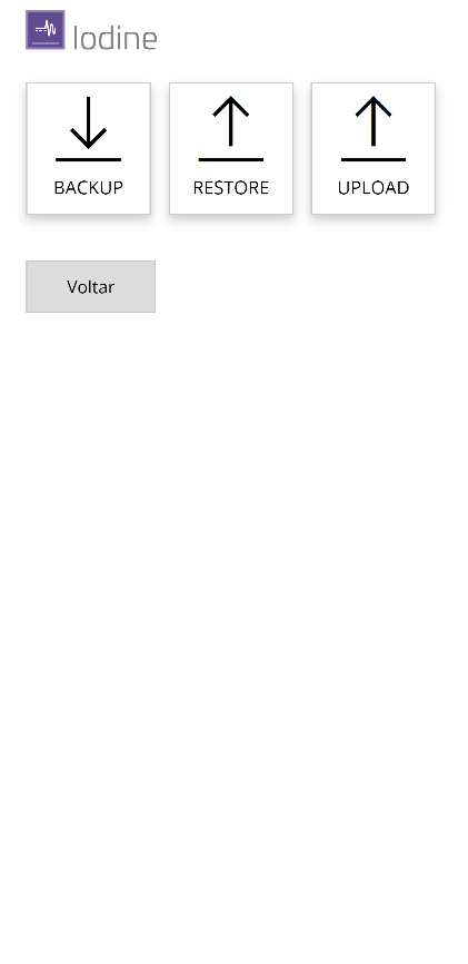
The Arquivos menu gives access to the following screens:
- Backup — creates and downloads a file with all the equipment's configuration data.
- Restore — sends a backup file to restore the settings.
- Upload — sends a specific file to the equipment.
Backup
Use this screen to download a file with all the equipment's configuration data.
Click Iniciar (Start) to download the file. A window will open asking where to save it. This file can be used in the Restore function when you want to restore the configuration. Click Voltar (Back) to return to the previous menu.
Restore
Use this screen to send a file with the equipment's configuration data. The file must be in the proper format, as created by the Backup function.
Click Escolher arquivo (Choose file) to select it and Enviar arquivo (Send file) to start the transfer. Click Voltar to return to the previous menu.
Upload
Use this screen to send a specific file to the equipment. The files must be in the proper format. The screen shows the space currently available in the equipment's memory.
Click Escolher arquivo to select it and Enviar arquivo to start the transfer. Click Voltar to return to the previous menu.
Upgrade
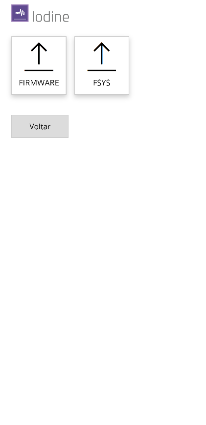
This function allows you to send a new firmware version to the equipment when necessary. There are two types of update:
- FIRMWARE — update of the executable code.
- FSYS — update of the file system.
In some situations both updates must be performed. Choose the type by clicking the specific button or click Voltar to return to the initial menu.
FIRMWARE Upgrade
Through this screen you select a file with a new firmware version to update the device.
Click Escolher arquivo to select the file and then Enviar novo firmware to start the transfer.
At the end of the update, the equipment will restart automatically. Since it will return to normal operation mode, the Access Point will be deactivated. To go back to configuration mode, press and hold the MODE button for 6 seconds again (see the Installation Manual).
FSYS Upgrade
Through this screen you select a file with a new version of the file system (FSYS) to update the device.
Click Escolher arquivo to select the file and then Enviar novo fsys to start the transfer.
At the end of the update, the equipment will restart automatically. Since it will return to normal operation mode, the Access Point will be deactivated. To go back to configuration mode, press and hold the MODE button for 6 seconds again (see the Installation Manual).
Info
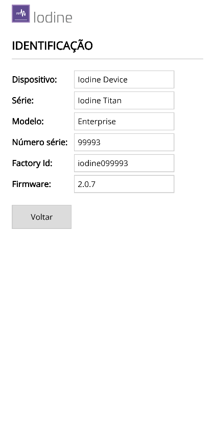
This page presents technical information about the equipment:
| Field | Description |
|---|---|
| Dispositivo (Device) | Device type. |
| Série (Series) | Device series. |
| Modelo (Model) | Device model. |
| Número de série (Serial number) | Manufacturing serial number. |
| Factory ID | Factory identification. |
| Firmware | Firmware version. |
Reboot
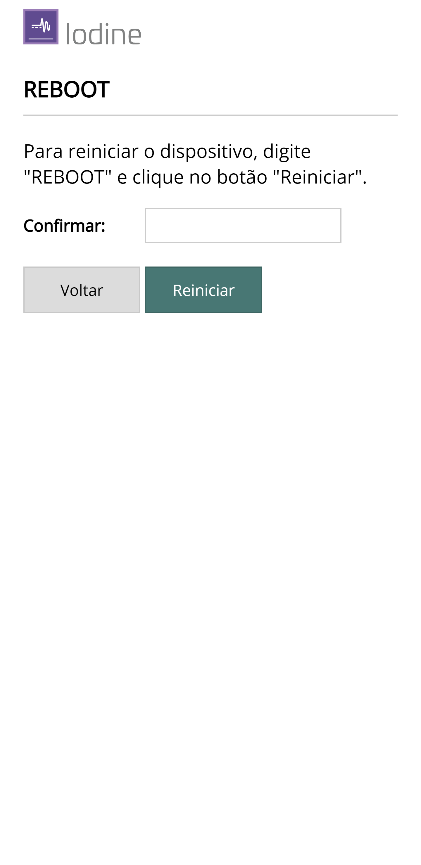
Use this function to restart the Iodine converter remotely.
Type REBOOT in uppercase letters in the confirmation field and click the Reiniciar (Restart) button.
Sh-400 QR Reader
The QR-SERIES variant of the Iodine uses the Sh-400 QR Code scanner on the input, converting the QR Code reading to the format required by the controller (for example, Abatrack). The Sh-400 is third-party equipment; this section documents only the configuration needed to use it with the Iodine.
The reader is programmed by scanning configuration barcodes: point the Sh-400 at the desired barcode and it applies the corresponding parameter. The codes below are ready to use with the Iodine.
Scan the barcodes in the order indicated in each block: the Start programming code, then the code of the desired parameter and, finally, End programming. The reader confirms each step with an audible/visual signal.
Serial configuration for the Iodine
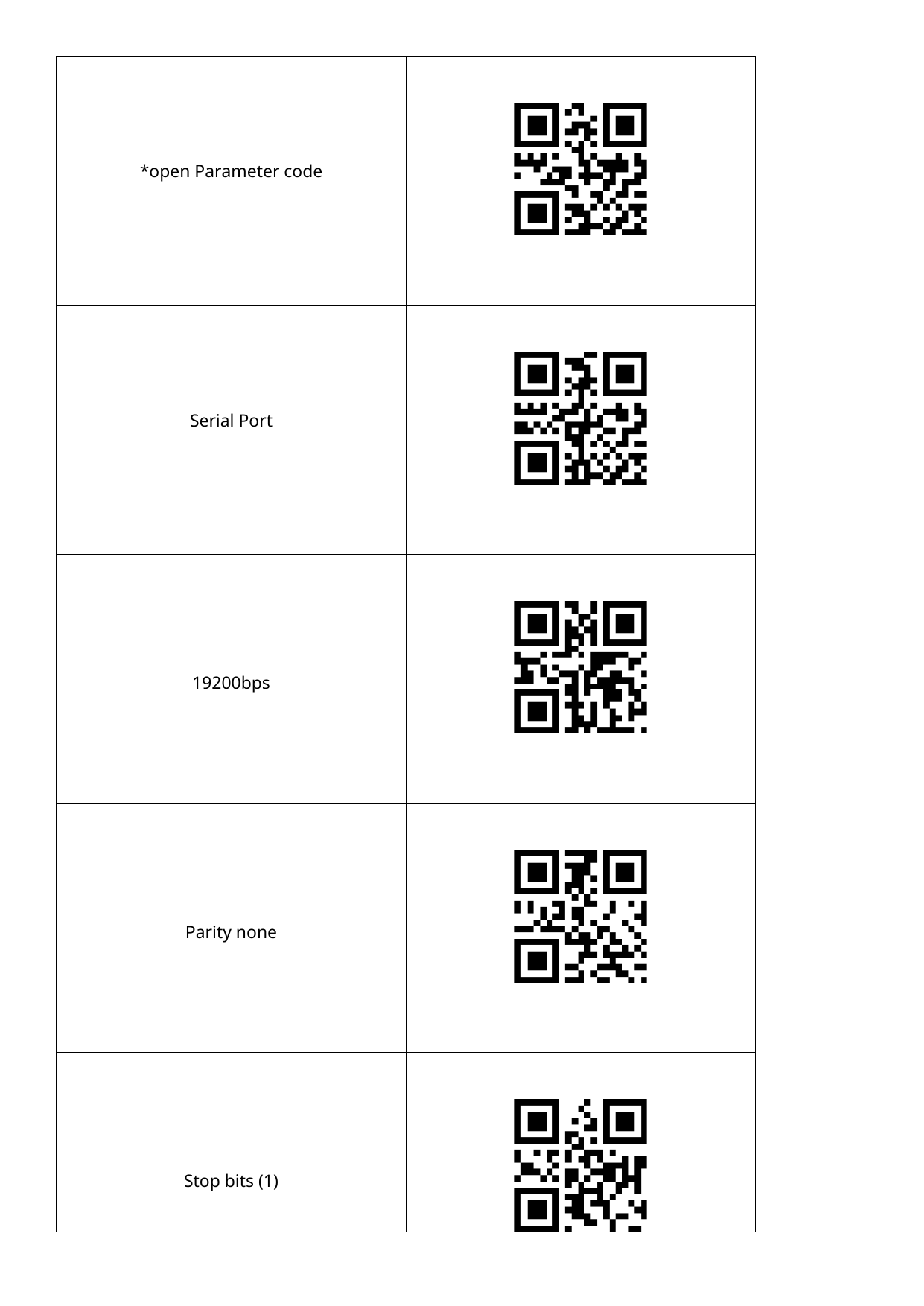
For the Sh-400 to communicate correctly with the Iodine's UART input, configure the serial port with the parameters below and the proper reading mode. Scan the barcodes in this sequence:
| Parameter | Value |
|---|---|
| Serial port | Serial Port (enables the serial output) |
| Baud rate | 19200 bps |
| Parity | None |
| Stop bits | 1 |
| Reading mode | Continuous Mode |
| Induction | Automatic Induction Mode |
| Illumination | Floodlight — Lighting when Read |
| Positioning light | Positioning lights — Lighting when Read |
Illumination and positioning light
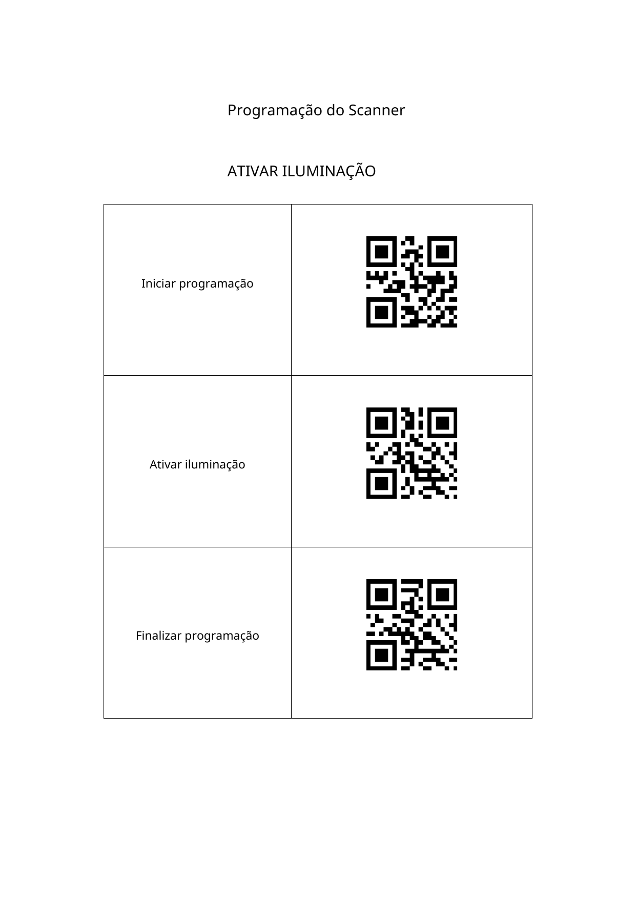
When necessary, the illumination (floodlight) and the positioning light of the Sh-400 can be enabled or disabled independently. Each adjustment is a block of three codes: Start programming, the enable/disable code and End programming.
| Adjustment | Action |
|---|---|
| Illumination | Enable illumination / Disable illumination |
| Positioning light | Enable positioning light / Disable positioning light |
Next Steps
- Installation Manual — power supply, connections (Wiegand/Abatrack, RS232 UART), voltage jumpers, RESET/MODE buttons and configuration mode.