Installation Manual - IRIDIUM I/O Module
This manual guides the designer or installer through the physical installation and the electrical connections of the IRIDIUM I/O module.
Power Supply
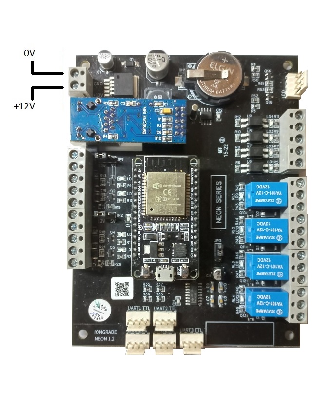
The I/O module must be powered with 12 VDC ±5%. Consumption is 120 mA (base, without peripherals) — up to 150 mA catalog rating.
| Specification | Value |
|---|---|
| Supply voltage | 12 VDC ±5% |
| Consumption | 120 mA (base, without peripherals) — up to 150 mA catalog rating |
Use a regulated power supply sized to support the I/O module and all connected peripherals.
Signal Inputs
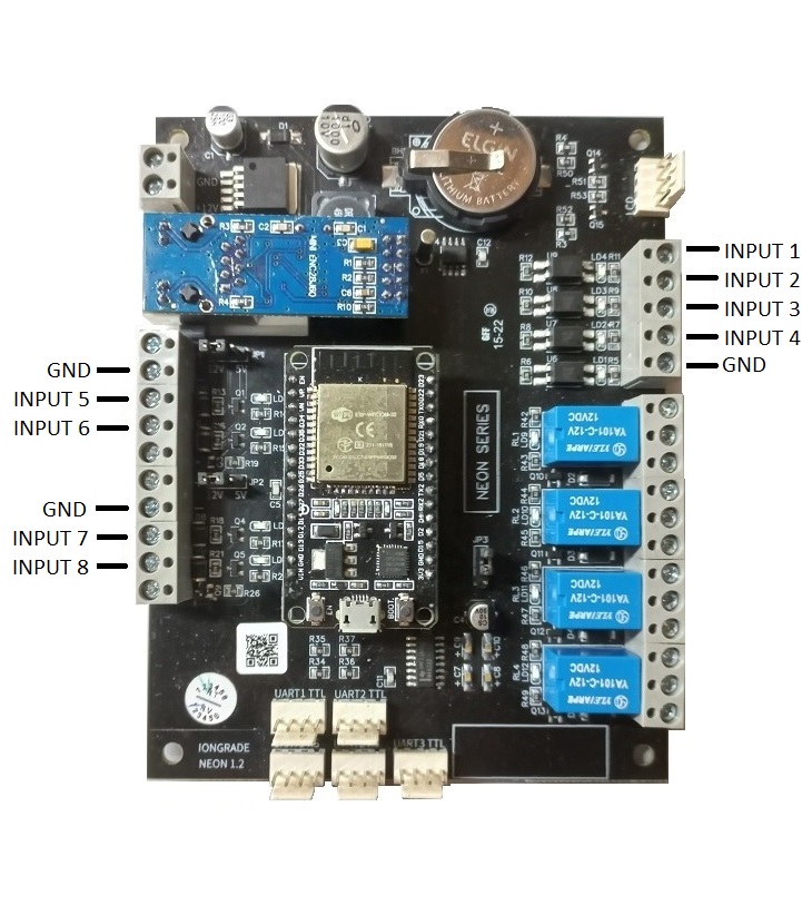
The I/O module has eight digital inputs (INPUT1 to INPUT8). These inputs are prepared to receive a dry contact, without power.
The contact triggers the input by connecting it to the device's own GND signal. When the input is connected to GND, it means input on (INPUT = 1).
Inputs INPUT1 to INPUT4 have isolated circuits with optical couplers and are therefore for preferred use.
Signal Outputs
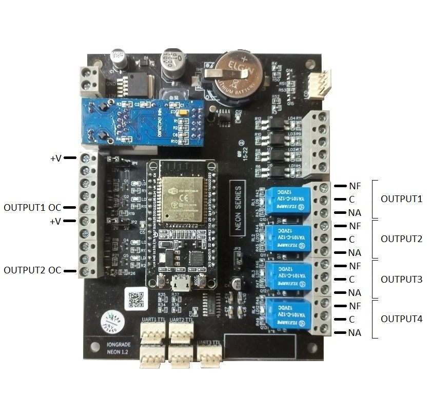
The device's signal outputs consist of four relays (OUTPUT1 to OUTPUT4) that can energize loads of 1A/120VAC or 2A/30VDC.
| Specification | Value |
|---|---|
| AC load | 1A / 120VAC |
| DC load | 2A / 30VDC |
Observe these limits to ensure the integrity and service life of the relay contacts.
Relay Pinout
Each relay has three terminals:
| Terminal | Function |
|---|---|
| NC | Normally Closed |
| C | Common |
| NO | Normally Open |
Open-Collector Outputs
In addition to the relays, the I/O module provides two open-collector digital outputs — OUTPUT1 OC and OUTPUT2 OC — that work in parallel with relays OUTPUT1 and OUTPUT2, but with a different electrical signal.
The circuits of these outputs consist of transistors with open collectors and will "conduct" to "zero" when the respective output is turned on. They can energize loads up to 100 mA, which must be connected between the +V terminals and the OUTPUT1 OC or OUTPUT2 OC output.
Serial Ports (UARTs)
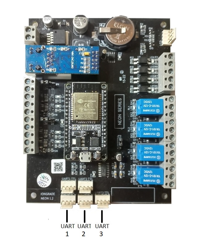
The I/O module has three serial communication ports. Ports UART1 and UART2 are available for connecting various configurable devices. They operate on the RS232 electrical standard and can supply 5VDC power to the connected device, such as scanners. The maximum current draw is limited to 150 mA on each port.
Serial port UART3 is used only for special applications and its voltage level is TTL 3.3V.
Serial Connector Pinout
UART1 and UART2 (RS232):
| Pin | Signal |
|---|---|
| 1 | +5 VDC |
| 2 | TX |
| 3 | RX |
| 4 | GND |
UART3 (TTL 3.3V):
| Pin | Signal |
|---|---|
| 1 | +3.3 VDC |
| 2 | TX |
| 3 | RX |
| 4 | GND |
LCD Display
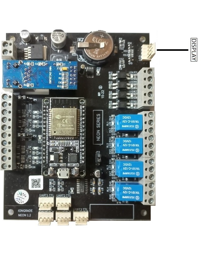
The I/O module is prepared for the connection of a display module (LCD) with I2C communication. The electrical level of the signals is TTL at 5VDC.
| Pin | Signal |
|---|---|
| 1 | GND |
| 2 | +5VDC |
| 3 | SCL |
| 4 | SDA |
Buttons and Indicators
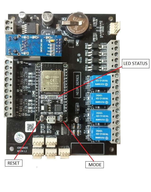
RESET button — forces the I/O module to reboot. Press it quickly to exit configuration mode.
MODE button — puts the I/O module into configuration mode. Press and hold for 5 seconds.
STATUS LED — provides information about the general state of the communication.
Reading the STATUS LED
When the I/O module is in operation mode, the STATUS LED provides information about the general state of the communication. Every two seconds a series of up to four quick blinks starts:
| Blink | Meaning |
|---|---|
| 1 | I/O module in operation mode |
| 2 | Network connection (Ethernet/WiFi) OK |
| 3 | Connection with the system Broker OK |
| 4 | Communication with the server OK |
When four blinks are counted in each cycle, the situation is normal. This check is very helpful during installation and maintenance for locating communication failures.
Starting the Configuration
The IRIDIUM I/O module is configured through a browser. To start the configuration, follow the steps below.
1. Activate Configuration Mode
- Press and hold the MODE button for 5 seconds.
- The I/O module will automatically boot into Configuration mode.
- The STATUS LED will keep blinking rapidly, indicating that the mode is active.
- The I/O module activates a WiFi access point (AP mode) and starts accepting client connections.
2. Connect to the I/O Module WiFi Network
The WiFi network created by the I/O module has a unique and exclusive name (SSID) for each device:
- Format:
iridium+ identification code - Examples:
iridium7512208F,iridium89C0CF6A
3. Access the Configuration Interface
-
Connect to the I/O module WiFi network.
-
Open the browser and go to:
http://192.168.4.1 -
Enter the default credentials:
- Username:
admin - Password:
iridiumpwd
- Username:
From here on, refer to the Operation Manual to configure each I/O module screen.
Installation Recommendations
- Location: install the I/O module in a place protected from the weather.
- Ventilation: ensure adequate ventilation for heat dissipation.
- Grounding: connect the grounding system properly.
- Cabling: use shielded cables in environments with interference.
- Protection: consider using surge protectors on the power supply.
Next Steps
After completing the physical installation, refer to the Operation Manual to configure the I/O module.