Installation Manual - Kalium Gateway
The Kalium has been discontinued and is no longer sold for new projects. This documentation remains available to support existing installations. For new projects or replacements, contact the Iongrade sales team.
This manual guides the designer or installer through the specification and installation of the electrical connections of the Kalium communication gateway.
Power Supply
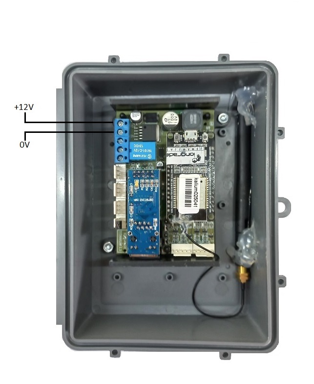
The gateway must be powered with 12 VDC ±5%. Consumption is up to 700 mA.
| Specification | Value |
|---|---|
| Supply voltage | 12 VDC ±5% |
| Consumption | up to 700 mA |
Use a regulated power supply rated to support the gateway and the load connected to the alarm relay.
Alarm Relay Connection
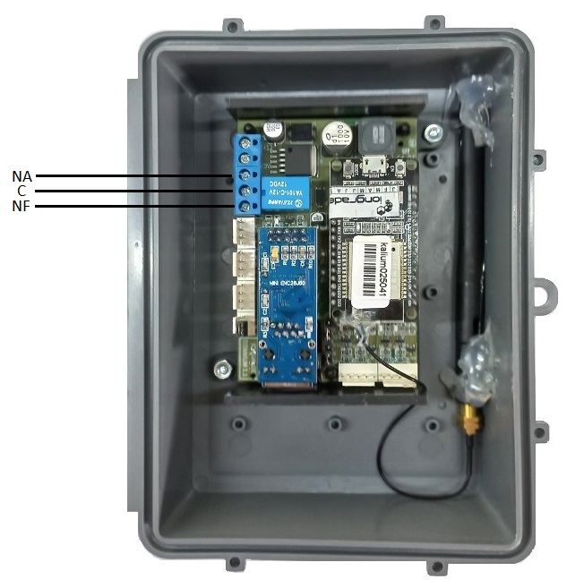
The gateway relay can energize loads with the following capacities:
| Specification | Value |
|---|---|
| AC load | 1A / 120VAC |
| DC load | 2A / 30VDC |
Observe these limits to ensure the integrity and service life of the relay contact.
The relay is triggered when a beacon belonging to a UID flagged as alarm is detected by the Scandium antennas. This way, the gateway can locally signal alarm/panic situations associated with specific beacons in the installation.
Buttons and LEDs
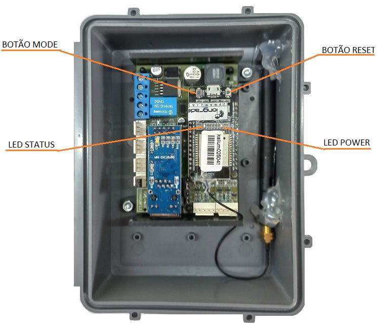
The gateway has two buttons that let you force a reset (boot) or switch it into configuration mode. It also has LEDs that show the power and communication status of the device.
| Button | Function |
|---|---|
| RESET | Forces the reset (boot). Press briefly to exit configuration mode. |
| MODE | Switches the gateway into configuration mode. Press and hold for 8 seconds. |
| LED | Function |
|---|---|
| POWER | Indicates the device power supply. |
| STATUS | Shows the overall communication status of the gateway. |
To put the gateway into configuration mode, press and hold the MODE button for 8 seconds. To force the reset (exit configuration mode), just briefly press the RESET button.
Reading the STATUS LED
When the gateway is in operation mode, the STATUS LED provides information about the overall communication status. Every three seconds a series of up to four quick blinks starts. When four blinks are counted in each cycle, the situation is normal. In the blink series, the meaning of each one is as follows:
| Blink | Meaning |
|---|---|
| 1 | The gateway is in operation mode |
| 2 | Connection to the Ethernet network is OK |
| 3 | Connection to the system Broker is OK |
| 4 | Communication with the system server is OK |
Checking these conditions through the STATUS LED helps a lot during installation and maintenance of the device, to locate communication failures.
When the gateway is in configuration mode, the STATUS LED blinks quickly and continuously, indicating that configuration mode is active.
Next Steps
- Overview — mesh system architecture, supported beacons, and specifications