Operation Manual - Neon Controller
The Neon controller has an internal HTTP server and all of its configuration is done through a browser. This manual describes each screen of the web configuration interface.
To access the configuration you must put the controller in Configuration mode, connect to the WiFi network it generates, and point the browser to 192.168.4.1. The step-by-step procedure is in the Installation Manual.
Login
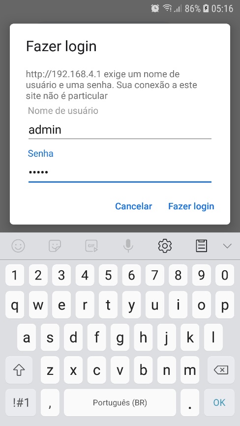
When you connect the browser to the controller, you will be prompted for a username and password. The default values are:
- Username:
admin - Password:
neonpwd
Main Menu
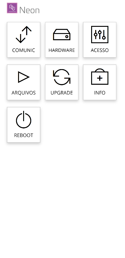
The initial configuration screen presents the following options:
- Comunic — configuration of the network communication parameters.
- Hardware — configuration of the devices physically connected to the controller.
- Acesso (Access) — configuration of the controller's control mode.
- Arquivos (Files) — backup and restore functions.
- Upgrade — controller firmware update.
- Info — general information about the controller.
- Reboot — restarts the device.
Communication
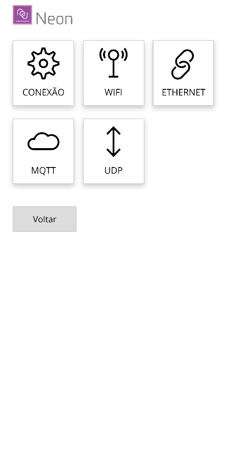
The Comunic menu gives access to the following screens:
- Conexão (Connection) — defines the media type (WiFi or Ethernet) used to connect the controller to the network while in operation.
- WiFi — WiFi network parameters, in case the controller uses a wireless connection.
- Ethernet — wired network parameters (RJ45 connector).
- MQTT — parameters for accessing the MQTT communication server (broker).
- UDP — parameters of the UDP communication channel.
Connection
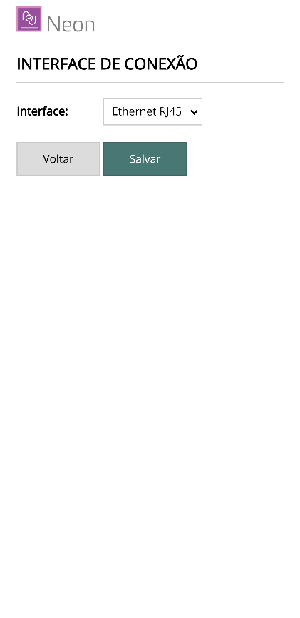
On this screen you define the media type the controller will use to connect to the communication network while in operation mode. The options are:
- WiFi (Wireless)
- Ethernet (RJ45)
Make the necessary changes and click Salvar (Save) to confirm.
WiFi
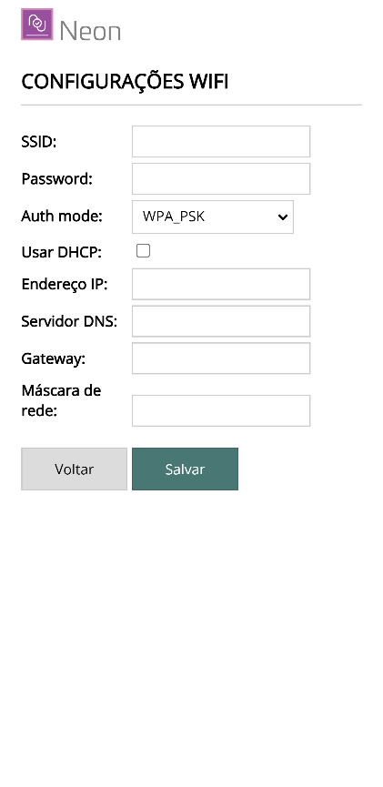
On this screen, enter the data and access parameters of the WiFi network that will be used in operation mode:
- SSID — WiFi network name.
- Password — network password.
- Auth mode — authentication mode (e.g.:
WPA_PSK). - Usar DHCP (Use DHCP) — when checked, obtains the IP automatically.
- Endereço IP (IP address) — static IP (when DHCP is disabled).
- Servidor DNS (DNS server) — DNS server address.
- Gateway — gateway address.
- Máscara de rede (Subnet mask) — subnet mask.
Make the necessary changes and click Salvar (Save) to confirm.
Ethernet
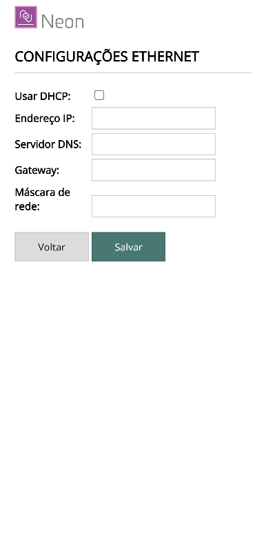
On this screen, enter the data and access parameters of the Ethernet network (RJ45) that will be used in operation mode:
- Usar DHCP (Use DHCP) — when checked, obtains the IP automatically.
- Endereço IP (IP address) — static IP (when DHCP is disabled).
- Servidor DNS (DNS server) — DNS server address.
- Gateway — gateway address.
- Máscara de rede (Subnet mask) — subnet mask.
Make the necessary changes and click Salvar (Save) to confirm.
MQTT
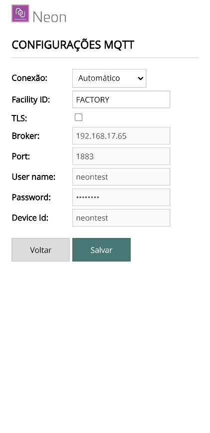
On this screen you enter the parameters to establish the connection with the MQTT communication server, along with information about the physical installation of the controller:
- Conexão (Connection) — whether the board should connect to the Accelero Cloud broker (Automatic), to a Custom MQTT broker, or to no broker.
- Facility ID — unique identification of the installation. All controllers in the same installation must have the same Facility ID (e.g.:
empresax,edificioz). - TLS — enables secure communication (Transport Layer Security). The server must allow this mode.
- Broker — URL address of the communication server.
- Port — number of the communication port with the broker.
- User name — username for broker access.
- Password — broker access password.
- Device Id — unique and exclusive identification of each controller in the installation (e.g.:
catraca1,porta2).
When the connection is made through Accelero Cloud, only the Facility ID parameter needs to be configured — exactly as defined in the control system that will manage the controllers.
Make the necessary changes and click Salvar (Save) to confirm.
UDP
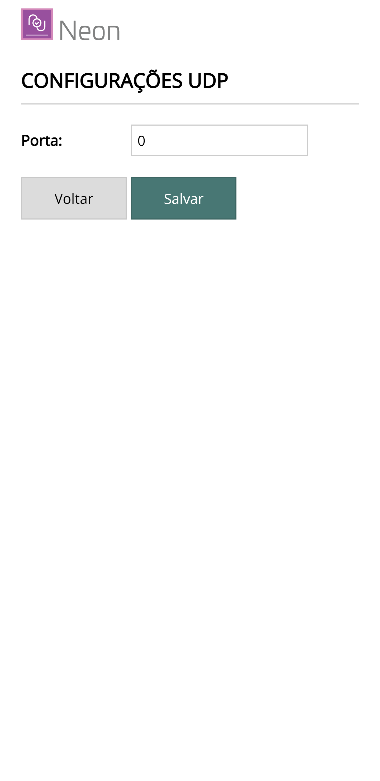
On this screen you enter the parameters to establish a connection using the UDP protocol. Through this connection, other equipment can send information to the controller — such as cards/tags read on other devices.
- Porta (Port) — communication port to be used. If it is set to
0(zero), the service is turned off.
When using the UDP connection, it is recommended that the controller's IP address be static, since this address must be configured in the equipment that will send data over this connection.
Hardware
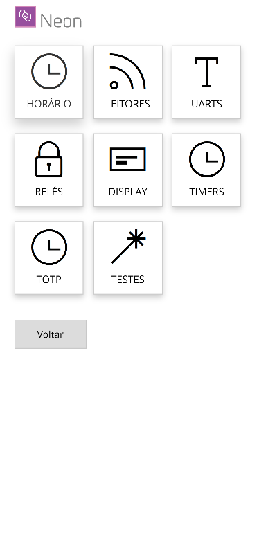
The Hardware menu gives access to the following screens:
- Horário (Clock) — adjustment of the controller's time and NTP server parameters.
- Leitores (Readers) — types of readers that will be connected to the controller.
- UARTS — types of devices connected to the serial ports.
- Relés (Relays) — operation mode and timing of the output relays.
- Display — display operation mode.
- Timers — general timings (password entry, biometrics, etc.).
- TOTP — TOTP (Time-based One-Time Password) parameters.
- Testes (Tests) — hardware operation tests.
Clock
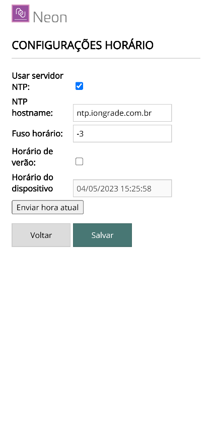
On this screen you can set the controller to keep its internal clock synchronized with an external date/time server (NTP Server):
- Usar servidor NTP (Use NTP server) — when checked, the controller uses an NTP server to adjust its local clock automatically.
- NTP hostname — URL of the NTP server.
- Fuso horário (Time zone) — time zone of the location where the controller is installed.
- Horário de verão (Daylight saving time) — automatically adjusts for daylight saving time.
- Horário do dispositivo (Device time) — current date and time of the controller.
- Enviar hora local (Send local time) — sends your computer's date/time to the controller.
Make the necessary changes and click Salvar (Save) to confirm.
Readers
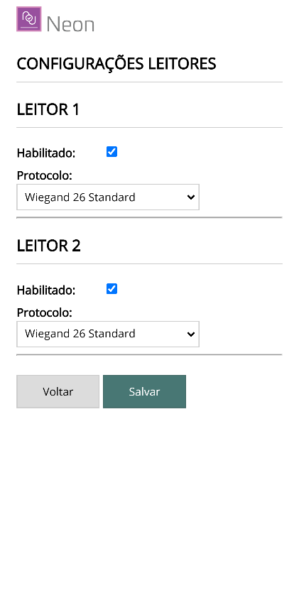
The Neon controller has interfaces for connecting card readers of the ABATrack, Wiegand, and other formats. On this screen, enter the type of reader that will be connected to each interface:
- Habilitado (Enabled) — activates or deactivates the reader.
- Protocolo (Protocol) — reader type (e.g.:
Wiegand 26 Standard, ABATrack, etc.).
Make the necessary changes and click Salvar (Save) to confirm.
UARTs
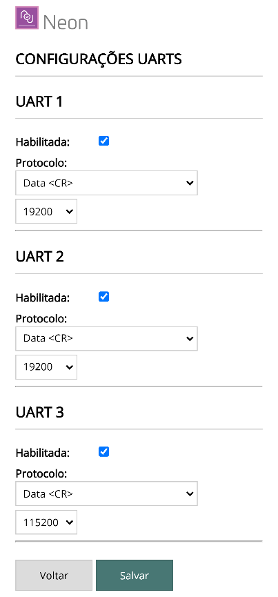
The Neon controller has communication ports (UARTs) for connecting various types of devices, such as QR Code reading modules, Bluetooth modules, biometric scanners, printers, etc.
- UART1 is associated with channel 1 and UART2 with channel 2.
- UART3 is used for special applications (e.g.: an IODINE for the card reader input of a visitor card collection bin).
On this screen, enter which type of device will be connected to each UART and click Salvar (Save) to confirm.
Relays
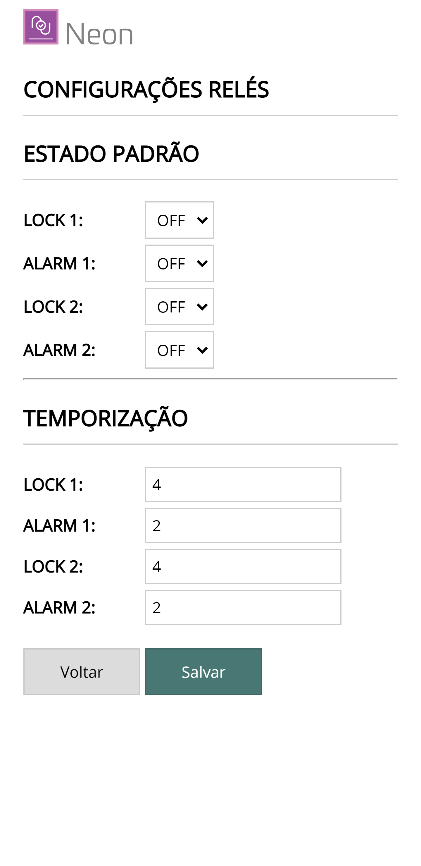
The Neon controller has four relays for triggering external devices (LOCK1, LOCK2, ALRM1, and ALRM2):
- The LOCK1 and ALRM1 relays are associated with channel 1; LOCK2 and ALRM2 with channel 2.
- The LOCK relay is activated whenever the controller grants access on the channel.
- The ALRM relays are activated in an access denied condition. In some control modes, the relays can take on other functions.
On this screen, configure the default state of each relay — off (OFF) or on (ON) — and the time (in seconds) each relay stays on when activated.
Make the necessary changes and click Salvar (Save) to confirm.
Display
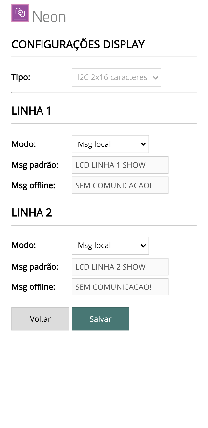
The Neon controller's display can operate showing locally generated messages (default) or showing the messages sent by the server.
This screen lets you choose the operation mode of each of the two display lines and define a standard message for the online/offline states when the chosen mode is that of server messages.
Make the necessary changes and click Salvar (Save) to confirm.
Timers
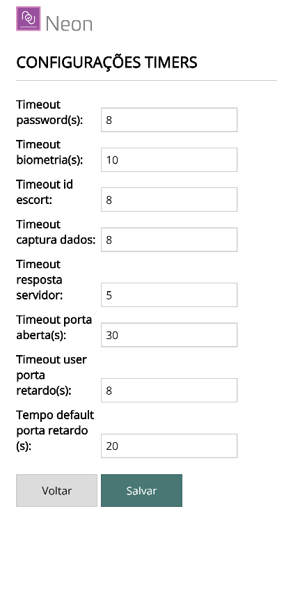
On this screen you set the time limits (in seconds) for some user actions:
- Timeout password — maximum time to wait for the user's password entry.
- Timeout biometria — maximum time to wait for biometric identification.
- Timeout escort — maximum time to wait for the identification of a companion.
- Timeout captura dados — maximum time to wait for card entry in capture mode (card creation).
- Timeout resposta servidor — maximum time to wait for the server's response to a query.
- Timeout porta aberta — time limit to generate an open door alarm.
- Timeout user porta retardo — maximum time to wait for the user's re-identification in Delayed Door mode.
- Tempo default porta retardo — timing adopted in Delayed Door mode when operating in contingency (offline).
Make the necessary changes and click Salvar (Save) to confirm.
TOTP
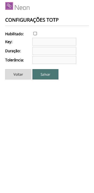
On this screen you set the parameters of the TOTP (Time-based One-Time Password) control:
- Habilitado (Enabled) — activates the TOTP functionality.
- Key — secret key to be used.
- Duração (Duration) — time window, in seconds, for TOTP validation.
- Tolerância (Tolerance) — number of tolerance time windows. This number of windows before and after the current time will be considered.
Make the necessary changes and click Salvar (Save) to confirm.
Tests
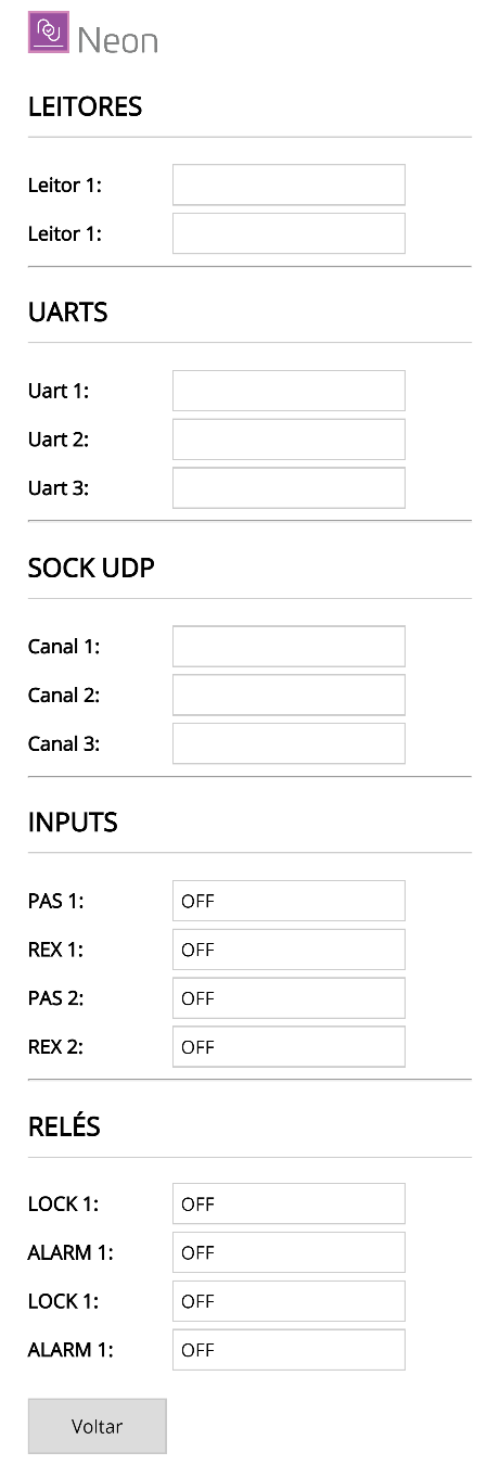
On this screen you can check the operation of the devices connected to the controller:
- When you present a card to one of the readers connected to the controller, the data read is shown on the respective channel.
- The state of the signal inputs (REX and PAS/DOOR) is also updated in real time on the screen.
Access
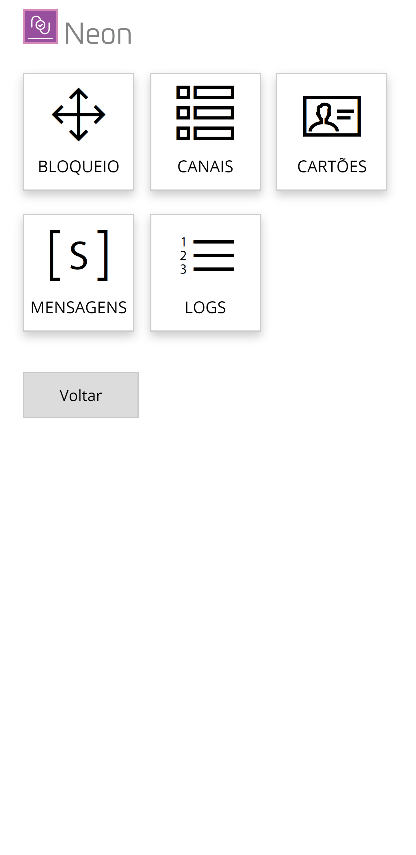
The Acesso (Access) menu gives access to the following screens:
- Bloqueio (Lock) — defines the type of device to be controlled (door, turnstile, barrier, etc.).
- Canais (Channels) — control characteristics of each controller channel.
- Cartões (Cards) — functions for adjusting the local card list.
- Mensagens (Messages) — configuration of the messages shown on the display.
- Logs — reading of the events recorded by the controller (used in stand-alone operation).
Lock
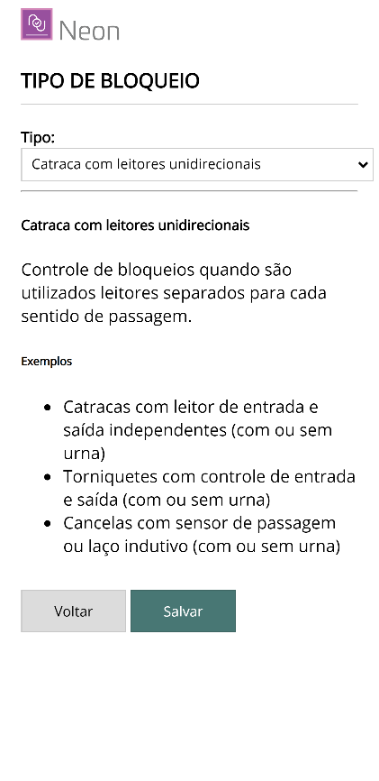
The Neon controller is prepared to control several types of devices. Use this screen to indicate which device it must control.
- Turnstile with unidirectional readers — complete turnstile: the first reader at the entry, the second at the exit, and the third installed in the visitor card collection bin.
- Turnstile with bidirectional reader — one bidirectional card reader and a second reader in the collection bin. The collection bin reader must be connected in the reader 3 position.
- Single door — control of one door with the first reader at the entry and the second at the exit.
- Two doors with unidirectional readers — control of two doors, with the first reader at the entry of the first door and the second at the entry of the second door. The exits are triggered by buttons on the REX1 and REX2 inputs.
- Two interlocked doors — control of two doors in interlocking mode (airlock). The state of the doors is monitored by the DOOR1 and DOOR2 inputs. Opening one door is only allowed if the other is closed.
- Interlocked combo door — control of one door in interlocking mode (airlock) with an external signal. The door state is monitored by the DOOR1 input and the release command is given by the LOCK1 relay. The DOOR2 input receives an external signal that enables/disables the operation, and the NO contact of the LOCK2 relay signals other Neon units that must block their operation. This way, two or more Neon units can perform interlocked control — you just connect the DOOR2 inputs and the LOCK2 relays of all Neon units in parallel, using a pair of wires.
- Two barriers with automatic passage — control of two vehicle barriers. Access is considered completed without the need for passage confirmation (PASS1 and PASS2 inputs).
- Delayed lock — control of a door with opening timing (delay configurable in the system). Upon authorization, the controller starts a timer and, at the end, requests the user's identification again — only on the second authorization is the lock released. During the timing, the LOCK2 relay stays on (useful for a signaling device). If an identifier flagged for duress is presented, the ALARM2 relay is activated during the process.
- Record - logger — passage logging mode only. The controller records the events, but does not perform any kind of control.
In Interlocked combo door mode, note that the pair of wires must respect the polarity of the DOOR2 inputs — one of the wires is connected to GND.
Make the necessary changes and click Salvar (Save) to confirm.
Channels
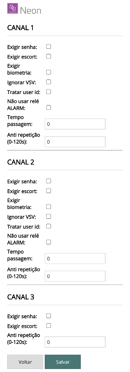
Specific verification rules can be defined for each control channel. Configure the parameters below and click Salvar (Save).
- Exigir senha (Require password) — enables offline password control on the channel. For it to work: the channel must be configured to verify the password, there must be a device with a keypad for password entry, and the user must have a password.
- Exigir escort (Require escort) — in offline mode, grants access to a user who requires an escort only when an authorized user releases their passage. For it to work: the channel must be flagged to verify companion, the user to be escorted must have the escort required flag, and the person granting the release must be flagged as an authorized companion (escort).
- Exigir biometria (Require biometrics) — requires the user to identify themselves through a biometric sensor. For it to work: the channel must be flagged to verify biometrics, there must be a biometric capture device associated with the channel, and the user must have registered biometric data.
- Ignorar VSV (Ignore VSV) — forwards access requests immediately to the server, without checking authorization in the local list.
- Tratar User Id (Handle User Id) — makes the controller accept the user's identification code as the identifier, instead of a card code (useful, for example, with a biometric scanner that sends the user code).
- Não usa relé ALRM (Do not use ALRM relay) — in case of access denied, does not activate the channel's alarm relay.
- Tempo passagem (Passage time) — period of time for the user to pass through the barrier. If it is shorter than the time defined for the channel's LOCK relay, Neon considers the relay time.
- Anti repetição (Anti-repeat) — time interval during which successive badge reads are ignored on the channel.
Cards
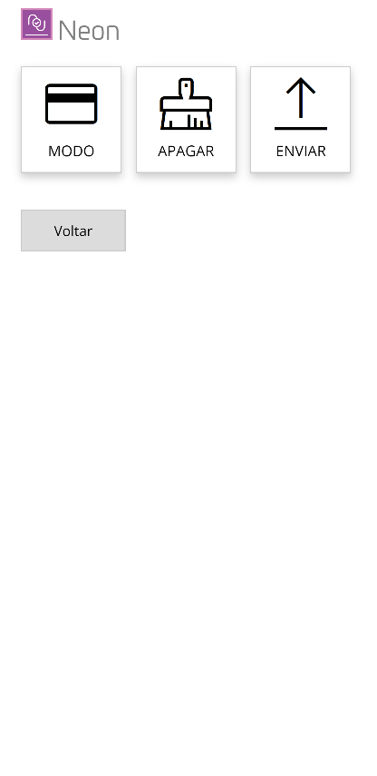
The Cartões (Cards) menu gives access to the following screens:
- Modo (Mode) — adjustment of the control mode of the user list stored in the controller's memory.
- Apagar (Delete) — deletes the data of the local card list.
- Enviar (Send) — upload of a card list for when the controller operates in fully stand-alone mode (without communication).
Mode
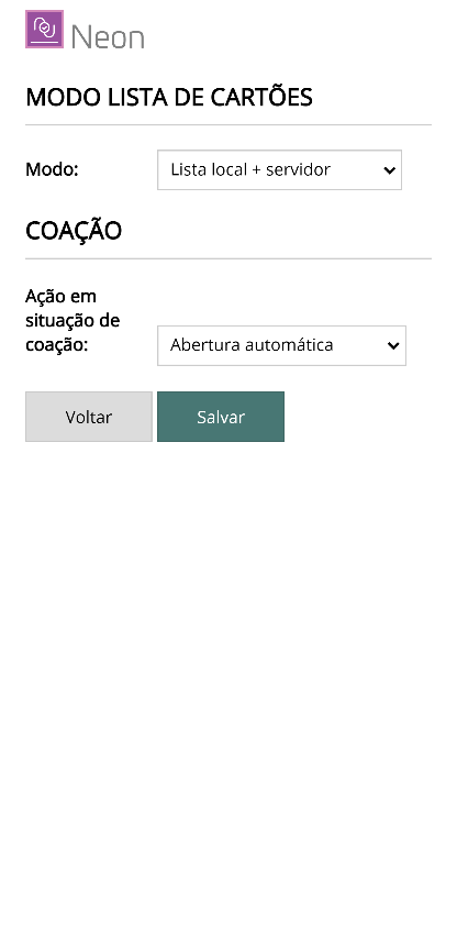
The Neon controller keeps a user list in its internal memory (local list), updated by the control software. Access control can use the local list and/or query the server. On this screen you define how the controller handles this list.
Card list:
- Lista local + servidor (Local list + server) — when communication is OK, the server is queried (except for cards flagged not to be queried). In case of a communication failure, the controller checks whether the user exists in its list in order to make the decision.
- Sempre consulta servidor (Always query server) — all requests are forwarded to the server. In case of a communication failure, the controller handles only duress cards locally.
- Nunca consulta servidor (Never query server) — uses only the local list for authorizations.
Duress — defines the controller's action when a card flagged as a "duress card" is presented in contingency mode (when online, the action is determined by the server):
- Abertura automática (Automatic opening) — authorizes access regardless of any other rule. Generates a "duress" event sent to the server when the connection is reestablished.
- Aplicar políticas de acesso (Apply access policies) — applies the access policies normally (which may block access), but generates a "duress" event sent to the server when the connection is reestablished.
Make the necessary changes and click Salvar (Save) to confirm.
Delete
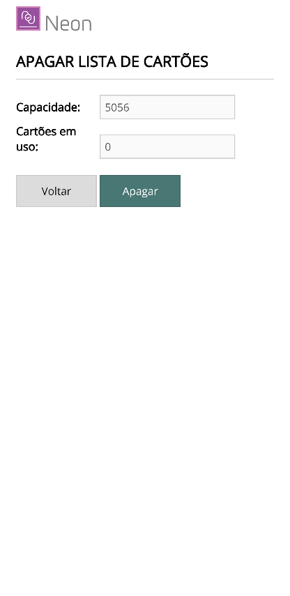
The screen shows the total capacity of the local card list and the number of cards in use. Use the Apagar (Delete) button to clear the local list.
Clearing the list can take a few seconds. Wait about 30 seconds and refresh the screen.
Send
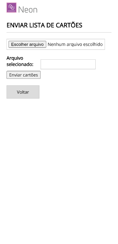
The Neon controller can operate in stand-alone mode (without communication and without control software). To do this, you must inform it about the users with access permission, their time ranges, etc. This function allows you to send a file with this data to the controller.
The file format is simple but standardized, and can be created in a text editor. Use the Escolher arquivo (Choose file) button to locate it and the Upload button to start the transmission.
Contact technical support about the card file format.
Messages
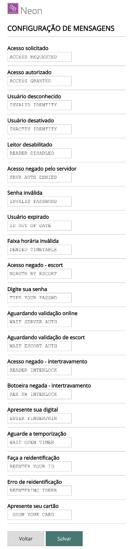
All the messages the controller shows on the display can be freely configured on this screen — for example: Access requested, Access authorized, Unknown user, Invalid password, Enter your password, Present your fingerprint, among others.
Make the necessary changes and click Salvar (Save) to confirm.
Logs
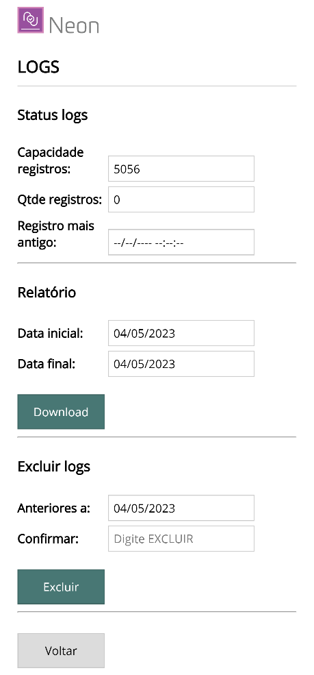
When the controller operates in stand-alone mode, event records continue to be stored in memory. This function lets you check the state of the records, generate a report (download), and clear the data:
- Status logs — storage capacity, current number of records, and date/time of the oldest record.
- Relatório (Report) — defines the start and end dates to create a file with the records for the period. The Download button creates and sends the file (standardized format).
- Excluir logs (Delete logs) — clears the event records. Enter the cutoff date and click Excluir (Delete).
Files
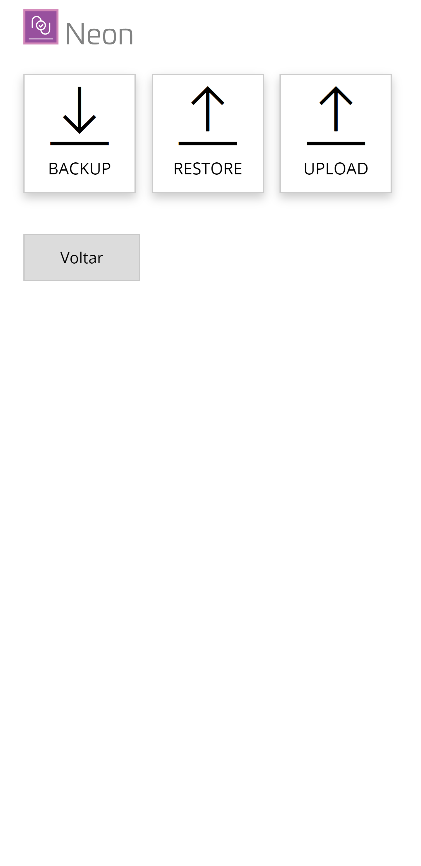
The Arquivos (Files) menu gives access to the following screens:
- Backup — creates and downloads a file with all the controller's configuration data.
- Restore — sends a backup file to restore the settings.
- Upload — sends a specific file to the controller.
Backup
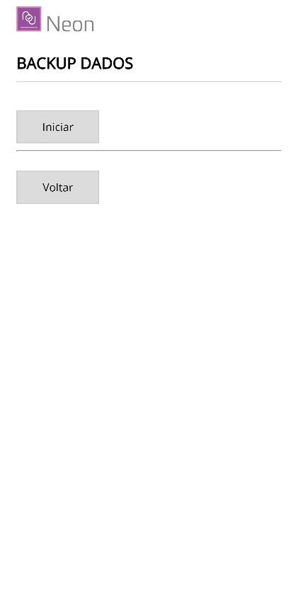
Use this screen to download a file with all the controller's configuration data.
Click Iniciar (Start) to download the file. A window will open asking where to save it. This file can be used in the Restore function whenever you want to restore the configuration. Click Voltar (Back) to return to the previous menu.
Restore
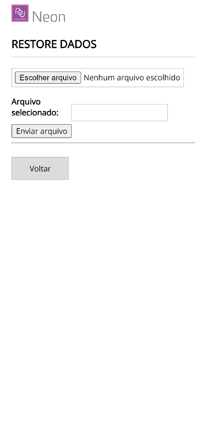
Use this screen to send a file with the controller's configuration data. The file must be in the proper format, as created by the Backup function.
Click Escolher arquivo (Choose file) to select it and Enviar arquivo (Send file) to start the transfer. Click Voltar (Back) to return to the previous menu.
Upload
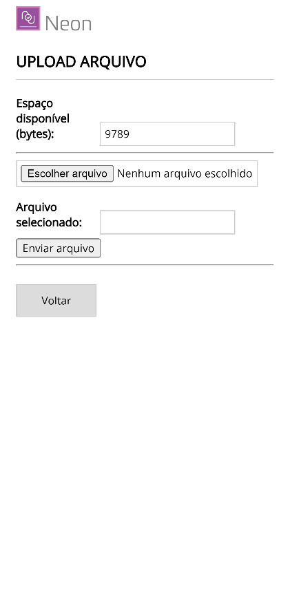
Use this screen to send a specific file to the controller. The files must be in the proper format. The screen shows the space currently available in the controller's memory.
Click Escolher arquivo (Choose file) to select it and Enviar arquivo (Send file) to start the transfer. Click Voltar (Back) to return to the previous menu.
Upgrade
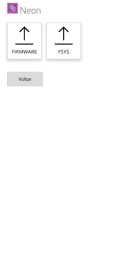
This function allows you to send a new firmware version to the equipment when necessary. There are two types of update:
- FIRMWARE — update of the executable code.
- FSYS — update of the file system.
In some situations both updates must be performed. Choose the type by clicking the specific button, or click Voltar (Back) to return to the initial menu.
Firmware
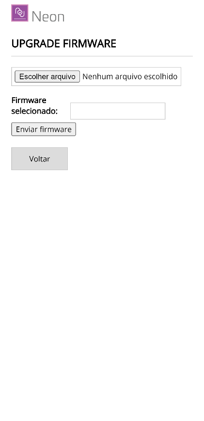
Through this screen you select a file with a new firmware version to update the device.
Click Escolher arquivo (Choose file) to select the file and then Enviar novo firmware (Send new firmware) to start the upload.
At the end of the update, the equipment will restart automatically. Since it will return to normal operation mode, the Access Point will be deactivated. To return to configuration mode, repeat the procedure described in Activating Configuration mode.
FSYS
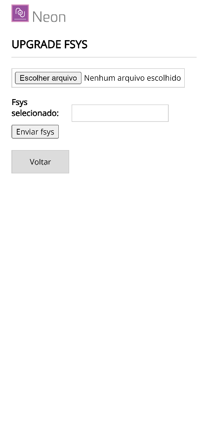
Through this screen you select a file with a new version of the file system (FSYS) to update the device.
Click Escolher arquivo (Choose file) to select the file and then Enviar fsys (Send fsys) to start the upload.
At the end of the update, the equipment will restart automatically. Since it will return to normal operation mode, the Access Point will be deactivated. To return to configuration mode, repeat the procedure described in Activating Configuration mode.
Info
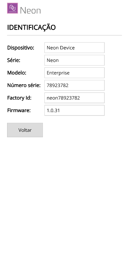
This page presents technical information about the controller:
- Dispositivo (Device) — device type.
- Série (Series) — device series.
- Modelo (Model) — device model.
- Número de série (Serial number) — manufacturing serial number.
- Factory Id — factory identification.
- Firmware — firmware version.
Reboot
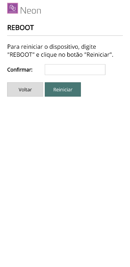
On this page you can restart the Neon remotely.
Type REBOOT in uppercase in the confirmation field and click the Reiniciar (Restart) button.
Status LED — Diagnostics
When the controller is in operation mode, the STATUS LED provides information about the general communication status. Every two seconds a series of up to four rapid blinks is initiated — four blinks per cycle indicate a normal situation:
| Blink | Meaning |
|---|---|
| 1 | The controller is in operation mode |
| 2 | The network connection (Ethernet or WiFi) is OK |
| 3 | The connection with the system's Broker is OK |
| 4 | Communication with the system's server is OK |
Four blinks every 2 seconds = system operating normally. Checking through the STATUS LED is very helpful during installation and maintenance for locating communication faults.
Troubleshooting
Does not communicate with the server
- Observe the STATUS LED (how many blinks per cycle) to identify at which stage the communication fails.
- Confirm the network settings (WiFi/Ethernet).
- Check the MQTT parameters (Broker, Port, Facility ID).
Reader does not read cards
- Check the reader voltage (jumpers JP1/JP2) — see the Installation Manual.
- Confirm the protocol configured in Hardware → Leitores (Readers).
- Use the Hardware → Testes (Tests) screen to check the reading.
Relay does not trigger
- Use the Hardware → Testes (Tests) screen.
- Check the timing configured in Hardware → Relés (Relays).
- Confirm the lock mode selected in Acesso → Bloqueio (Access → Lock).