Third Reader - Neon Controller
This manual explains how to add a third reader to the Neon access controller.
When to Use a Third Reader
There are situations in which a third reader is required on the Neon access controller. These are the cases where you must control a turnstile with a visitor card collection bin.
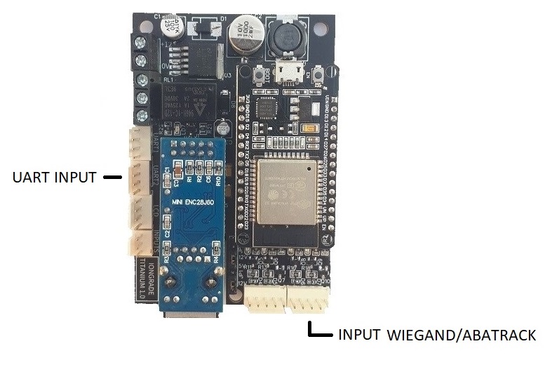
The third reader is added through the controller's UART3, using an IODINE module and an RS232/TTL electrical level converter. The steps below describe the complete procedure.
The collection bin reader must be connected in the reader 3 position. The lock mode definition (e.g.: Turnstile with unidirectional readers) is done on the Acesso → Bloqueio (Access → Lock) screen — see the Operation Manual.
1. Adding the IODINE Module
An IODINE module is used, and the third reader is connected to it. The reader technology can be ABATrack/Wiegand or Serial (UART) — the IODINE module accepts all of these technologies. Refer to the IODINE equipment manual for further details.
2. Configuring the IODINE Module Data Output
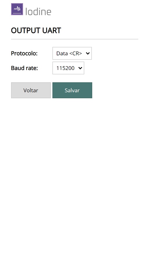
The data output (OUTPUT UART) of the IODINE module must be configured to operate with the DATA<CR> protocol and a baud rate of 115200.
| Parameter | Value |
|---|---|
| Protocol | DATA<CR> |
| Baud rate | 115200 |
3. Configuring the Neon Controller Data Input
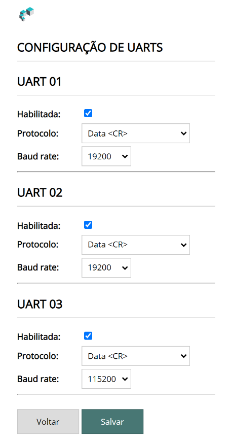
The Neon controller's UART3 must be enabled and configured to operate with the DATA<CR> protocol and a baud rate of 115200. The configuration is done on the Hardware → UARTS screen (see the Operation Manual).
| Parameter | Value |
|---|---|
| Protocol | DATA<CR> |
| Baud rate | 115200 |
4. The RS232/TTL Electrical Level Converter
The electrical signal level of the Neon controller's UART3 is 3.3V TTL, while the IODINE module's OUTPUT UART interface uses the RS232 electrical level. To connect the equipment, the electrical signals must be converted, which is done through an RS232/TTL converter.
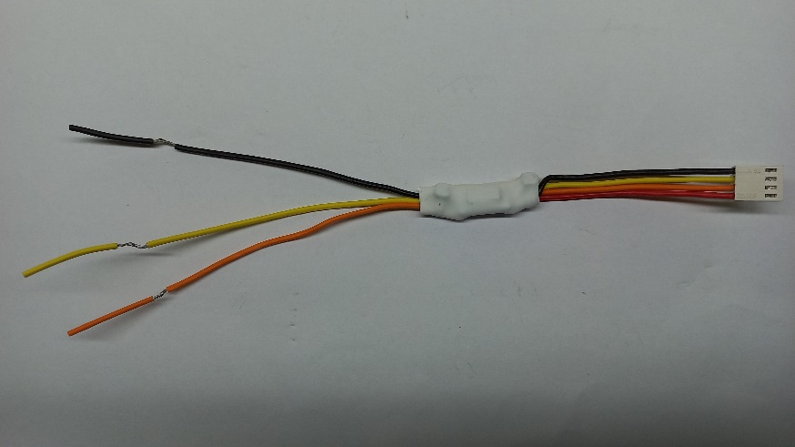
The connector side of the converter must be connected to the Neon controller's UART3 TTL. The wire side has the following identification:
| Wires | Signal |
|---|---|
| Black | GND |
| Yellow | RX |
| Orange | TX |
5. Connecting the RS232/TTL Converter to the Neon Controller
Connect the RS232/TTL converter to the Neon controller's UART3 (connector side).
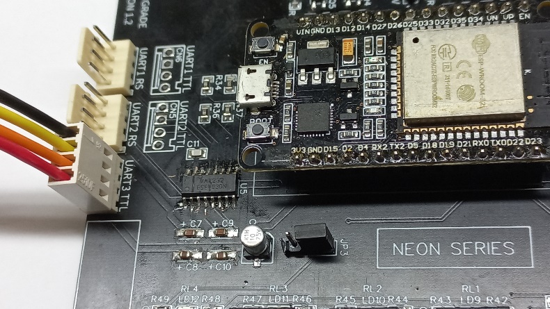
The converter's wire side uses the RS232 electrical level and must be connected to the IODINE module on the UART OUTPUT connector.
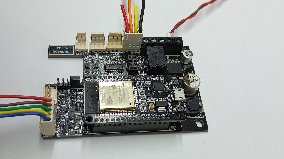
The IODINE module is supplied with a pigtail that has a 4-way KK connector for connecting to the UART.
On the IODINE side, only the Black (GND) and Orange (IODINE TX) wires are used — the others must be cut and insulated. For this connection you can use a multi-conductor cable of 24 AWG gauge or larger.
6. Wiring Overview
The OUTPUT UART data output of the IODINE module is connected to the Neon controller's UART3 using the RS232/TTL electrical level converter.
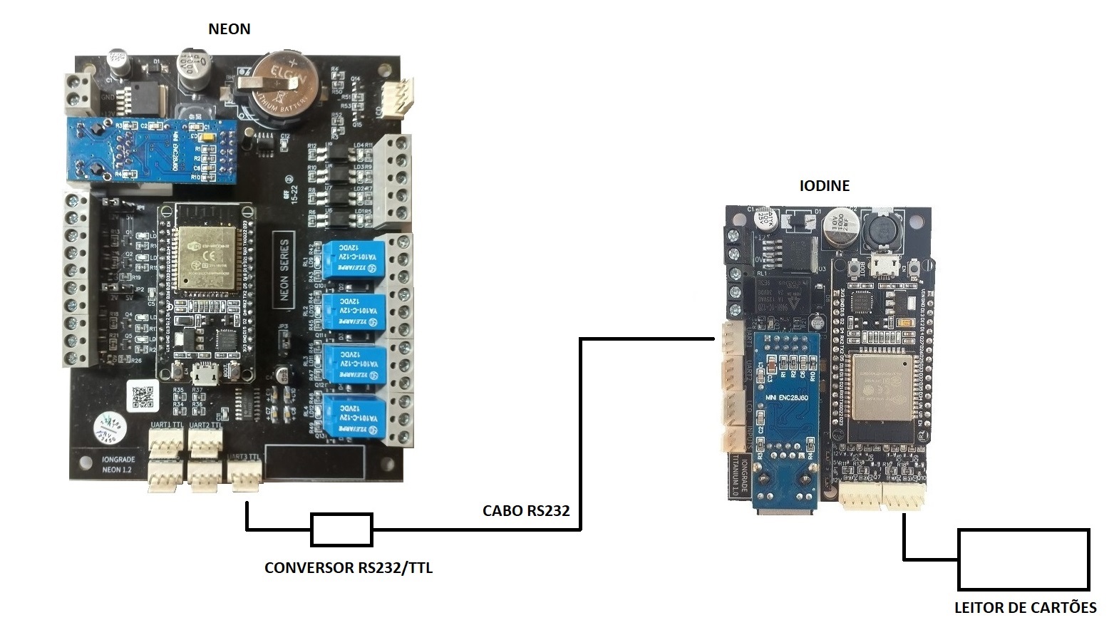
The connection of the converter's output wires (RS232 cable) to the IODINE module must follow the table below:
| Converter wires | Signal | Where to connect on the IODINE |
|---|---|---|
| Black | GND | Connect to Black (GND) |
| Yellow | RX | Connect to Orange (TX) |
| Orange | TX | Do not connect |
Next Steps
- Overview — features and specifications of the Neon controller
- Installation Manual — electrical connections and serial ports (UARTs)
- Operation Manual — UART configuration through the web interface