Installation Manual - Radium
Electrical connections, signaling and first access to the RADIUM gateway. This manual assumes basic familiarity with IP networks, MQTT, BLE and WiFi/Ethernet.
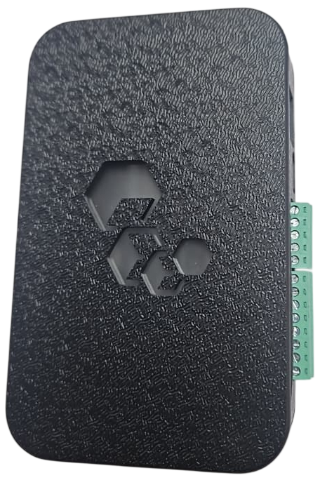
Power Supply
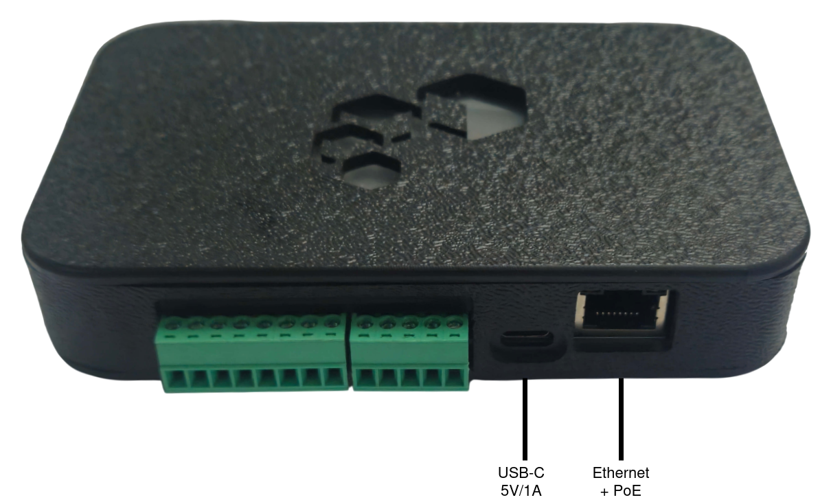
The RADIUM can be powered in two ways, and manages the transition between them automatically:
| Source | Specification |
|---|---|
| USB | USB-C, 5 V / 1 A minimum |
| PoE | Power over Ethernet — IEEE 802.3at Class 2, powered through the network cable itself |
There is also an internal battery that takes over when all external sources go down. The portal's Info page shows the active power source and the battery state.
The internal battery has a nominal capacity of 1000 mAh. In normal operation the typical runtime is 6 hours continuous; with the power-saving profile enabled it reaches about 10 hours.
Ethernet Connection (RJ45)
The RJ45 port runs at 10/100-Base-T and can use automatic IP (DHCP) or a static IP. It supports 802.1X authentication (EAP-MD5 or PEAP/MS-CHAPv2) when the network requires an authenticated port.
When the network cable also supplies power (PoE), the same port handles both network and power.
Inputs (IN1–IN4)
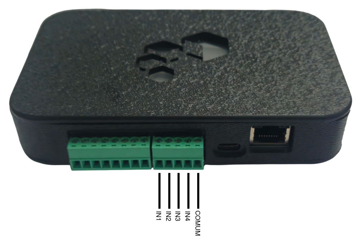
The gateway has 4 digital inputs (IN1 to IN4). Each input can be enabled and set as normal or inverted, and its state is shown live in the portal (Hardware ▸ Inputs).
On the Hardware ▸ Alarms page, each input is given a role:
| Role | What it does |
|---|---|
| None | The input triggers nothing. |
| Panic | Feeds the panic-by-input alarm. |
| Tamper | Feeds the tamper alarm. |
| Drive output | Mirrors the input directly onto a chosen output, bypassing the alarm engine. |
The inputs are for dry contact (voltage-free) — do not apply voltage to the terminals. Use them for wired panic buttons, tamper sensors, door contacts and other dry signals.
Outputs (S1–S4)
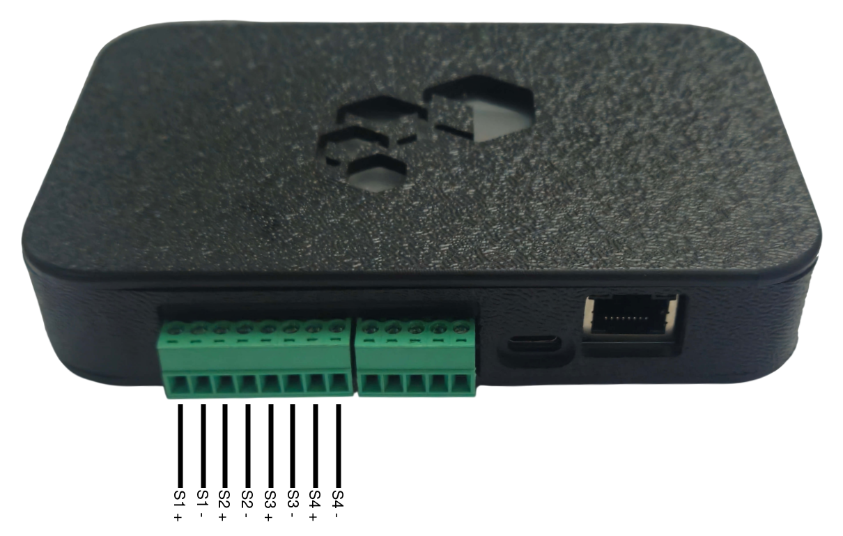
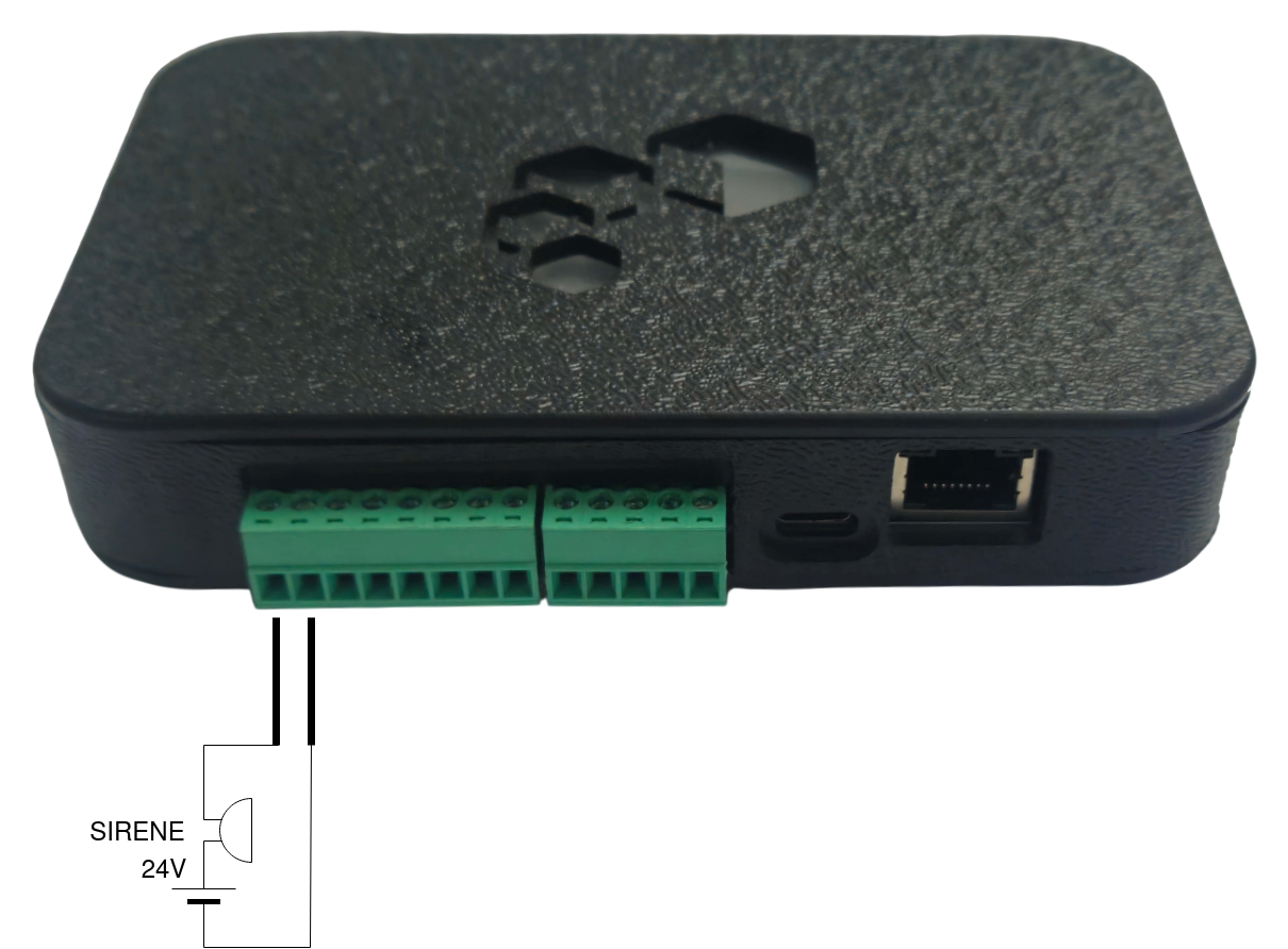
The gateway has 4 outputs (S1 to S4) to drive signaling devices, sirens, locks and other loads commanded by the alarms.
Each output has a default state — normal mode (rests off) or inverted (rests on) — and can be tested manually in the portal (Hardware ▸ Outputs). The activation time of each output is defined per alarm, on the Alarms page.
The default alarm-to-output mapping is:
| Output | Default alarm |
|---|---|
| S1 | Panic (beacon and input) |
| S2 | Gateway battery |
| S3 | MQTT offline |
| S4 | Tamper |
This mapping is configurable on the Alarms page.
The outputs are electronic and handle up to 24 V / 1 A each. They have polarity — mind the + and − when wiring, as in the example below:
Magnetic Sensor and Status LED
The RADIUM has no physical buttons. Field commands are given through a magnetic sensor (Hall effect), and the state is indicated by an RGB LED on the top of the product.
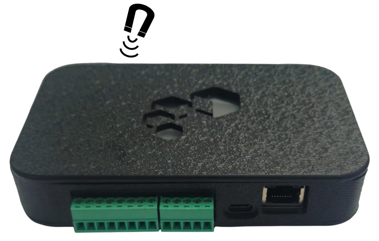
Holding the magnet near the indicated spot for about 3 seconds puts the gateway into configuration mode (portal): the LED fades up in white and gives a double blink to signal when to release.
At boot, the LED runs a color self-test (red → green → blue).
LED Colors
| Color | Meaning |
|---|---|
| Blue | Boot (starting up) |
| Green | Operating normally, everything OK |
| Yellow | Operating with a restriction (problem), with a blink code |
| Red | No communication (offline), with a blink code |
| White | Entering configuration mode / portal active |
| Magenta | Firmware update (OTA) in progress |
Blink Codes
When there is a problem, the yellow or red color blinks N times:
| Blinks | Meaning |
|---|---|
| 1 (red) | No network interface up |
| 1 (yellow) | Online, but running on the backup link (not the primary one) |
| 2 | MQTT down (broker unreachable) |
| 3 | Hardware / system failure |
| 4 | Gateway battery low |
| 5 | Clock not synchronized (NTP) |
With more than one problem at the same time, the LED shows only the most severe, in this order: no network (1 red) → MQTT down (2) → backup link (1 yellow) → hardware failure (3) → low battery (4) → clock not synchronized (5).
A beacon or input PANIC never appears on the LED — it is a silent alarm, for safety. The LED reflects only the board's health.
The LED can also be adjusted (brightness, on/off, signal problems only) on the Hardware ▸ LED page.
Accessing the Configuration
All configuration is done through a browser, in the portal served by the board itself. There are three steps:
1. Enter configuration mode
Hold the magnet near the magnetic sensor for about 3 seconds. The LED fades up in white and gives a double blink indicating when to release. The gateway then creates its own WiFi network and activates the portal; the LED stays white while the portal is up.
2. Connect to the gateway's WiFi network
The access point created by the gateway has a unique name per board and is password-protected (WPA2):
| Item | Value |
|---|---|
| SSID | The board's serial number itself (e.g., radium260001) once it has been provisioned; or radium_XXXXXX (derived from the MAC) while it has not |
| Password | radiumXXXX — the last 4 characters of the MAC, in uppercase |
3. Open the browser on the gateway
Connected to the gateway's WiFi network, point the browser to http://192.168.4.1 and log in.
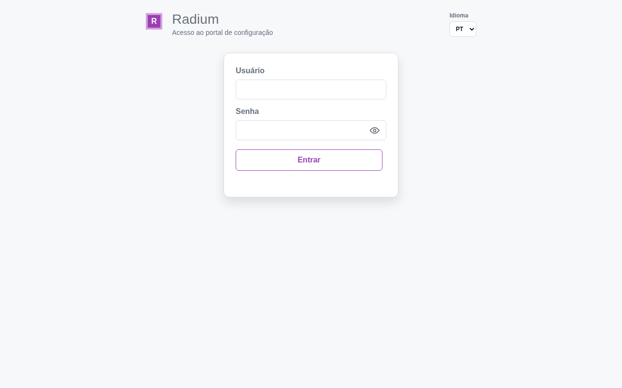
| Account | User | Factory default password |
|---|---|---|
| Normal (common) | radium | radiumpwd |
The factory default password is public in this manual — a default password known in the field is the same as having no password. The change is made through the integrator account (see Installation Commissioning).
The portal leaves configuration mode by itself after about 10 minutes without activity (the gateway restarts and goes back to normal operation); the login session expires after 30 minutes without use.
Installation Recommendations
- Position the gateway with the BLE coverage of the zone in mind — it is the antenna that hears the beacon with the strongest RSSI that defines the zone estimated by the platform.
- Prefer PoE where the infrastructure allows: a single cable run solves both network and power.
- Reserve the dry-contact inputs for signals that need a local reaction (panic button, tamper sensor).
- Make sure the maintenance team knows where the magnet is kept: without it there is no way to enter configuration mode, since the board has no buttons.
Next Steps
- Operation Manual — the configuration portal, page by page
- Installation Commissioning — power profile and beacon registration
- Overview — architecture and technical specifications