Selenium — Button Control Variant (KB)
The Selenium KB variant is the elevator button use control gateway (manual version v1.0, Jul/2022). Unlike the advance call variants (AS and TK), it does not call the elevator: it individually enables or blocks the floor buttons on the control panel, releasing to the user only the floors for which they have permission in the Accelero system.
This page covers only what is specific to the KB variant: architecture, RUBIDIUM modules, terminal blocks, UARTs, relay↔floor mapping and interconnection cables. The common configuration trunk (configuration mode, gateway Comunicação (Communication)/NTP/Backup/Upgrade) is in Operation and Configuration. The gateway's base hardware is the Titanium controller board running gateway firmware.
What Button Use Control Is
In button use control, each floor button on the elevator panel is wired to a relay. When a user is identified at the access controller, the KB gateway releases only the relays corresponding to the floors allowed for that user; the other buttons remain blocked. The user enters the elevator and can only press the floors they have access to.
The SELENIUM_KB gateway is the communication interface between the Accelero system and the RUBIDIUM relay modules, which are connected to the elevator button panel. The gateway receives from Accelero the information about the users authorized to use the elevator and passes on to the RUBIDIUM modules which relays (floors) must be released.
The KB variant controls button use, it does not perform the elevator advance call. It is the Selenium AS and Selenium TK variants that make advance calls, integrating with the elevator manufacturer's management system.
Typical Architecture
The KB solution is made up of two distinct pieces of hardware:
- SELENIUM_KB gateway — Titanium board with gateway firmware. It interfaces with the access controller and with the relay modules.
- RUBIDIUM module — Neon series board with 4 actuation relays. Each relay enables/blocks one floor button. Several modules can be interconnected in a daisy-chain (cascade).
The connection flow is:
Access controller → SELENIUM_KB gateway (UART1) → RUBIDIUM modules (UART2, in daisy-chain) → elevator button panel
- The gateway's UART1 is connected to the access controller, which sends the code of the user with authorized access.
- The gateway's UART2 is connected to the series of RUBIDIUM modules. The connection is made from the gateway's UART2 to the UART2 of the first RUBIDIUM module in the series, and the UART1 of the last module in the series closes the bus back to the gateway.
- Each RUBIDIUM module has 4 relays; use as many modules as needed for the total number of elevator buttons. There is no limit to the number of RUBIDIUM modules subordinate to the gateway.
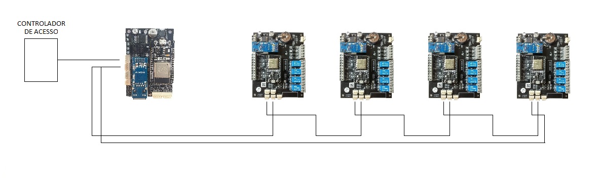
SELENIUM_KB Gateway Connections
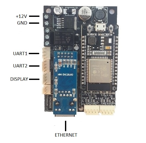
The gateway is powered by 12 VDC, with a consumption of 120 mA. Use of the display is optional. The board exposes the following terminal blocks and interfaces:
| Terminal / Interface | Function |
|---|---|
+12V, GND | Gateway power supply from an external 12 VDC source |
UART1 | Serial port connected to the access controller, which sends the code of the user with authorized access |
UART2 | Serial port connected to the RUBIDIUM modules (first module in the series) |
DISPLAY | Display connection (optional use) |
INPUTS | Signal inputs |
ETHERNET | RJ45 connector for wired UTP 10/100-Base-T network |
Size the 12 VDC power supply to support the gateway and the set of RUBIDIUM modules powered in the installation.
Defining the network media (WiFi/Ethernet), NTP, backup/restore and gateway upgrade follows the common procedure described in Operation and Configuration. The configuration of the serial ports (the gateway's UARTS screen) is also detailed there: by default UART1 receives the data from the access controller and UART2 connects to the RUBIDIUM module, and there is no need to change these values except under special conditions.
The RUBIDIUM Module
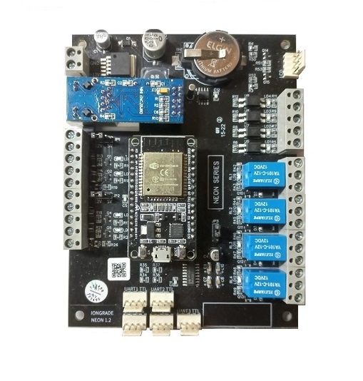
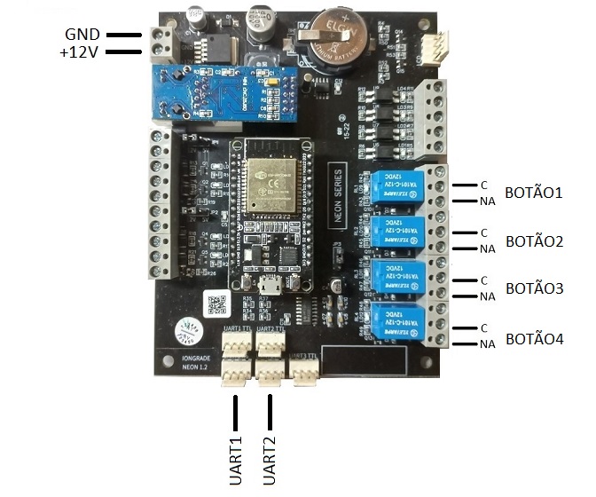
RUBIDIUM is a Neon series board with 4 actuation relays and RS232 serial communication (UART1 and UART2 ports). It is powered by 12 VDC, with a consumption of 150 mA. Each relay enables or blocks one floor button on the elevator panel. The relays are wired to the elevator control panel; during module configuration, each relay is associated with the floor served by the elevator.
RUBIDIUM serial ports
| Port | Function |
|---|---|
UART1 | Connected to the next RUBIDIUM module in the series. If it is the last module in the series, it is connected to the SELENIUM_KB gateway |
UART2 | Connected to the SELENIUM_KB gateway (if it is the first module in the series) or to the UART1 of the previous module |
This UART1/UART2 pinout is what allows the daisy-chain connection: the gateway enters the UART2 of the first module, each module passes on through its UART1 to the next, and the UART1 of the last module closes the series back to the gateway.
LEDs and operation state
When powered on, the module enters normal operation. The state can be checked through the LEDs:
| LED | Indication |
|---|---|
STATUS | Every three seconds it starts a series of up to two quick blinks. Under normal conditions 2 blinks are counted per cycle: blink 1 = module in operation mode; blink 2 = connection to the gateway (or to the previous RUBIDIUM module) is OK |
RX | Signals the reception of messages coming from the gateway (if it is the first in the series) or from the previous RUBIDIUM module |
TX | Signals the sending of messages to the next RUBIDIUM module or to the gateway (if it is the last in the series) |
The behavior of the STATUS LED is a great help in locating communication faults during installation and maintenance. In configuration mode, the STATUS LED keeps blinking rapidly, indicating that this mode is active.
RUBIDIUM Configuration Screens
Each RUBIDIUM module has its own configuration web server. Access follows the same pattern as the gateway (configuration mode via the BOOT button, its own WiFi access point with SSID rubidium…, browser at address 192.168.4.1). The default access values are user admin and password rubidiumpwd. The module's Hardware menu contains the two screens specific to KB: RELÉS (Relays) and UARTS.
RELAYS Screen — relay↔floor mapping
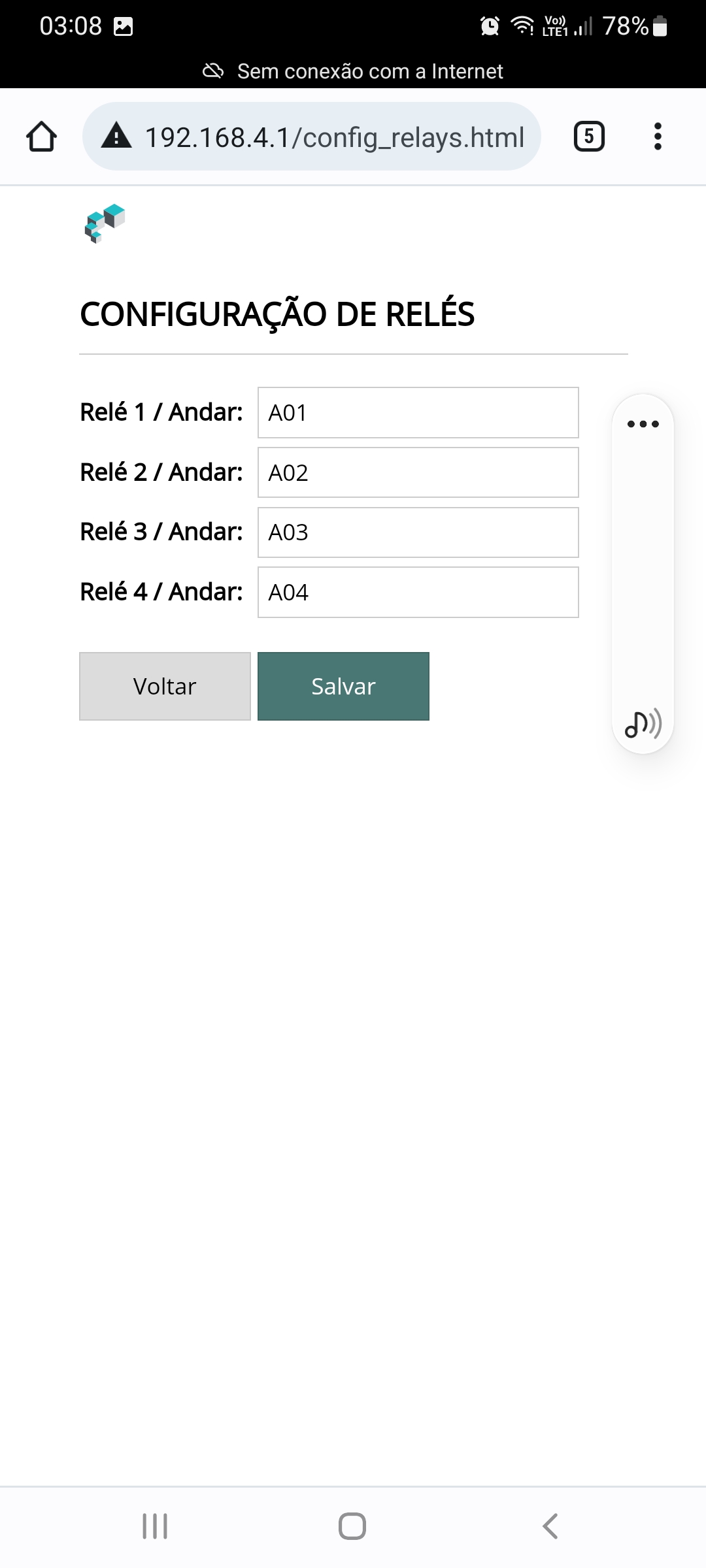
On this screen you associate each relay of the module with the floor it commands. It is the relay↔floor mapping that defines which button each relay enables.
| Field | Description |
|---|---|
| Relay (1 to 4) | Each of the 4 relays of the RUBIDIUM module |
| Floor | Identification of the floor commanded by that relay |
The floor identification must be entered exactly as configured in the Accelero system. After making the changes, click Salvar (Save) to confirm.
UARTS Screen
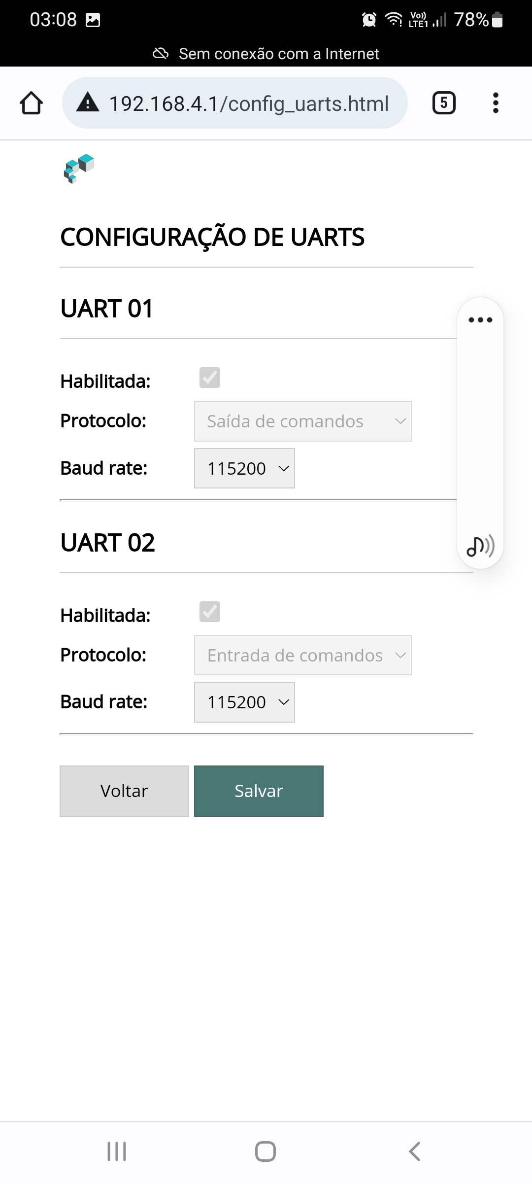
On this screen you configure the module's serial ports (UARTS). The default configuration is shown on the screen itself and there is no need to change it, except under special conditions.
| Field | Description |
|---|---|
| UART1 | Transmits the data to the next RUBIDIUM module or to the gateway (if it is the last in the series) |
| UART2 | Receives the data from the gateway (if it is the first in the series) or from the previous RUBIDIUM module |
| Speed | Communication speed of the port — the only changeable parameter |
Only the communication speed of the ports can be changed; the function of each UART cannot be changed. After making the changes, click Salvar to confirm.
Interconnection Cables
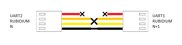
The KB solution uses three interconnection cables between the elements of the architecture. Follow the diagram of each cable for the correct pinout.
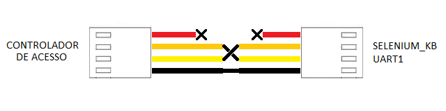
Access controller ↔ SELENIUM_KB cable
Interconnects the serial port of the access controller to UART1 of the SELENIUM_KB gateway, through which the code of the user with authorized access arrives.
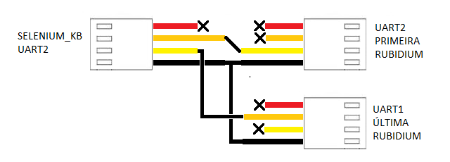
SELENIUM_KB ↔ RUBIDIUM cable
Interconnects the gateway's UART2 to the UART2 of the first RUBIDIUM module in the series.
RUBIDIUM ↔ RUBIDIUM cable
Interconnects RUBIDIUM modules in a daisy-chain: the UART1 of one module connects to the UART2 of the next module, chaining the series.
Next Steps
- Selenium Overview — variants, common features and technical specifications
- Operation and Configuration — configuration mode, Comunicação/NTP, Backup and gateway Upgrade
- Titanium Controller — the gateway's base hardware