I/O and Automation
ACCELERO lets you perform automation actions through the use of I/O devices. It is possible, for example, to monitor the inputs of one device and command the outputs of other devices depending on the status of what was read.
You can create several rules for the most different situations, ensuring wide flexibility for the configuration.
Controllers
The system's I/O devices are configured as normal controllers through the Settings > Controllers menu. Based on the type of registered device, the system identifies that it is an I/O module and enables the specific functions for that controller.
In addition to dedicated I/O devices, you can use and monitor the inputs/outputs (I/O) of common access controllers. The Cobalt controller works in mixed mode (I/O + access), unifying both functions in a single device.
Inputs/Outputs
Each I/O device has a different number of inputs and outputs. All of the controller's inputs/outputs are listed on the Inputs/outputs tab.
For each item, you can:
- Define a friendly name (e.g., "Main Door Sensor", "External Siren")
- Enable/disable that specific input/output
Disabling an input/output only means it will not be available in the selection screens. It does not change the physical operation of the hardware.
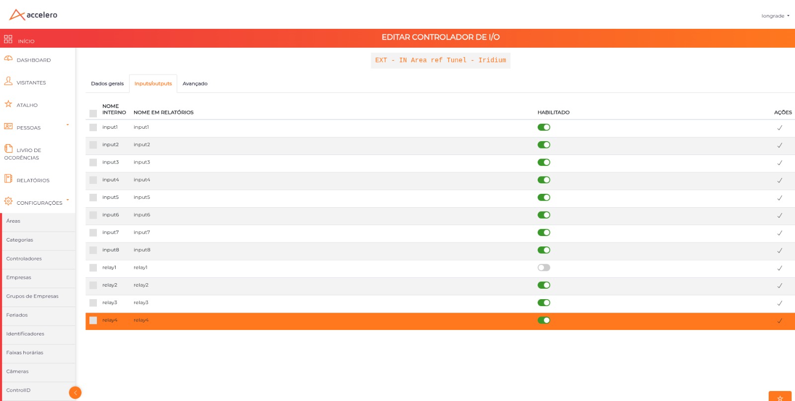
Once the controller is configured, its inputs/outputs will be available for performing automation actions.
Advanced
The Advanced tab gathers the data the equipment itself reports to ACCELERO, plus parameterization sub-tabs (General data, NTP, I/O and UART).
Under General data, below the "The data below was reported by the controller" notice, the following are displayed in read-only mode:
| Field | Description |
|---|---|
| Controller ID (alias) | Identifier reported by the equipment (e.g. iridium025557) |
| Current version | Firmware version in use |
| Last communication | Date and time of the equipment's last contact with the server |
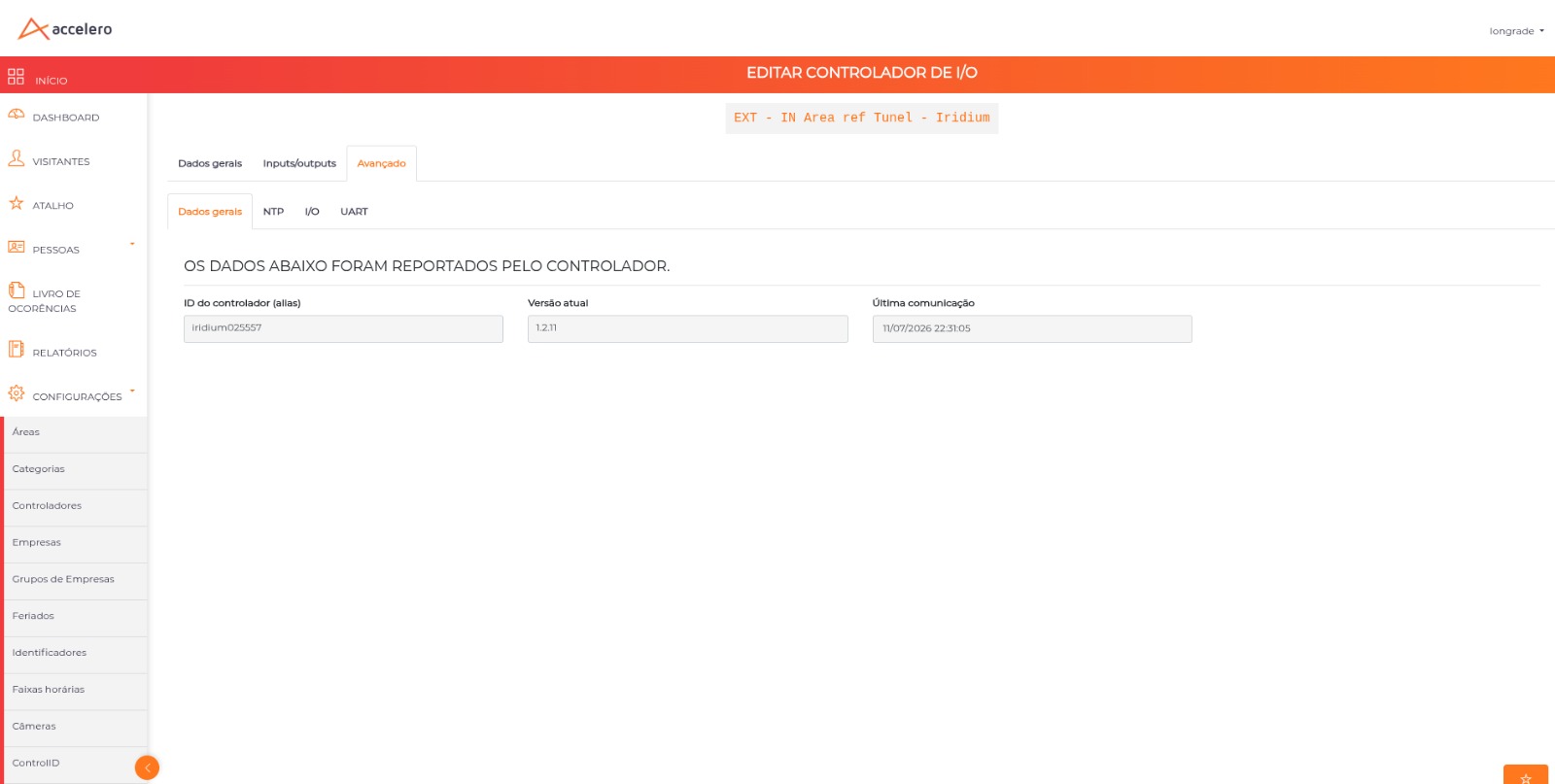
The remaining sub-tabs read and write the configuration on the board itself, not in the ACCELERO database. That is why they all provide two buttons:
| Button | Function |
|---|---|
| Fetch configuration | Reads the current configuration from the equipment and fills in the screen |
| Update configuration | Sends the changes to the equipment (asks for confirmation) |
The fields are only filled in after Fetch configuration. Saving without fetching first may write blank values to the equipment.
NTP
Date and time synchronization of the controller.
| Field | Description |
|---|---|
| Use NTP Server | Enables NTP synchronization |
| NTP Server | Address of the time server |
| Time zone | Time zone of the equipment |
| Control daylight saving time | Automatically applies the daylight saving time adjustment |
I/O
Electrical behavior of the board's physical inputs and outputs — not to be confused with the Inputs/outputs tab, which only names and enables the points inside ACCELERO.
The screen has two tables, Inputs and Outputs, with the same columns:
| Column | Description |
|---|---|
| Input / Output | Point number |
| Default state | Resting state of the point |
| Information duration (seconds) | How long the state is held/reported |
The number of rows follows the hardware of each model. On the Iridium, for example, there are 8 inputs and 4 outputs.
UART
Serial ports of the controller, used to connect readers and peripherals.
| Column | Description |
|---|---|
| UART | Serial port number |
| Protocol | Communication protocol of the port |
| Baud rate | Communication speed |
| Enabled | Turns the port on or off |
On the Iridium there are 2 UART ports.
See Controllers for general configuration.
I/O Handlers
When you want to register a new I/O automation in the system, just navigate to the I/O > Configure I/O menu and create a new I/O Handler.
Each handler is a set of rules and actions that must be taken. Several handlers can be created to act on the same inputs/outputs if necessary.
It is up to the user to ensure there will be no internal loops between handlers (actions of one handler triggering rules of another in a cycle).
After defining a name for the handler and clicking Save, the configuration screen will be shown with the tabs described below.
Concepts
An I/O handler is a service that:
- Monitors certain variables (triggers)
- Performs a series of checks (rules)
- Executes configured actions
What Variables Are
Variables are abstract entities that may (or may not) be related to physical entities:
| Variable Example | Type |
|---|---|
| Input of a device | Physical |
| Relay state of an I/O device | Physical |
| Number of people in a system area | Virtual (system) |
| Any text such as "abc" | Virtual (user) |
Important characteristics:
- Variables can be created and used at any time, without the need for prior creation
- Some variables are provided automatically by the system and presented in picklists (the inputs of a controller, for example)
- Others can/must be typed manually by the user as needed
General Data
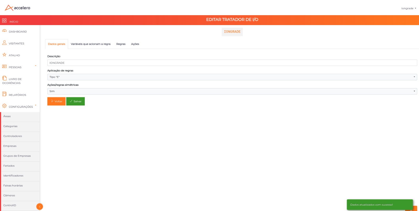
The General data tab presents basic information about the handler:
| Configuration | Description |
|---|---|
| Description | Name of the handler |
| Rule application | Defines whether the rules are of the AND type or the OR type. In the AND type, the actions will be executed if all rules are true. In the OR type, the actions will be executed if any one of the rules is true. |
| Symmetric actions/rules | If set to NO, the handler applies the actions only when the rules have a "true" state. If set to YES, the handler applies the actions when the rules are true and also applies the actions "in reverse" when the rules are false. |
The "Symmetric actions/rules = YES" option is useful when you want, for example, to turn on an output when the rule is true and automatically turn it off when the rule becomes false, without needing to create a second handler.
Variables That Trigger the Rule (Triggers)
The handler needs to know at what moment it should apply/re-apply the rules. This tab determines which variables will be the triggers of the check.
How it works:
- When any of the variables defined on this tab has any status change, the handler will run the checks and perform the necessary actions
- It is most common for the rule variables to be the trigger variables themselves, but this is not mandatory
In some situations, the handler should be executed from external triggers. For example: pressing a button connected to the input of a board can be the trigger, while the rules check completely different variables.
Rules
This tab defines all the check rules that determine whether the handler state is TRUE or FALSE.
For each rule, you must define:
| Field | Description |
|---|---|
| Variable | Which variable will be analyzed (it can be physical, like a device input, or virtual) |
| Comparison | Comparison operator (equal to, greater than, less than, etc.) |
| Reference value | The value against which the variable will be compared |
| Persistence time | How long that value must remain valid before considering the rule as true |
Examples:
Rule 1: INPUT01 OF DEVICE X must be EQUAL to 1 (ON) for more than 5 SECONDS
Rule 2: The VARIABLE ABC must be GREATER THAN 1000 for 0 SECONDS
Several rules can be configured at the same time. The application logic (AND or OR type) is defined on the General data tab of the handler.
Include a screenshot of the Rules tab showing rule configuration with variable, comparison, value, and time.
Actions
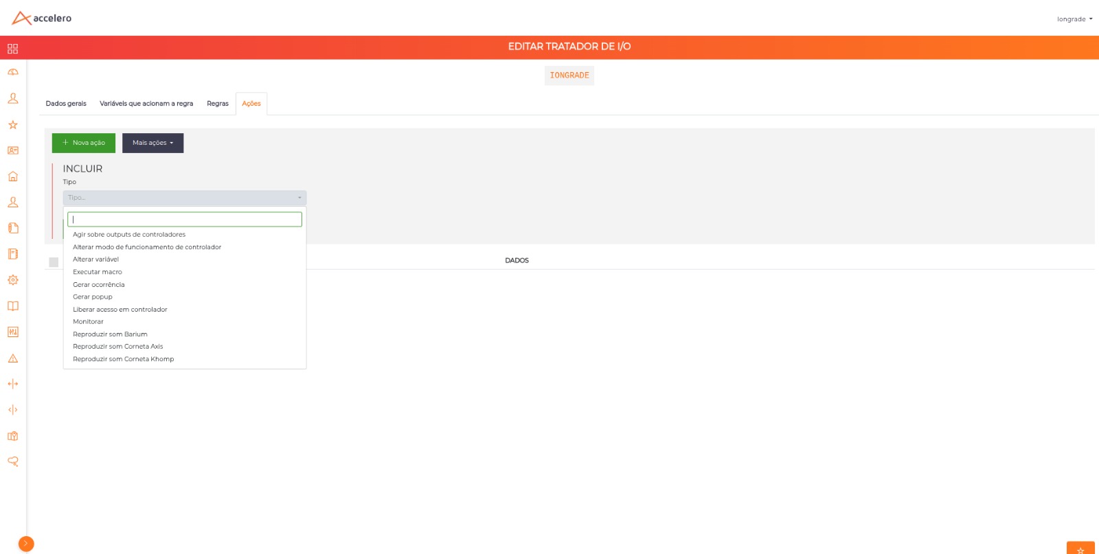
This tab defines which actions must be executed depending on the result of the rules. More than one action can be configured. The following actions are available:
1. Act on Controller Outputs
The system can act on controller outputs, turning them on or off.
Just select which controller/output should be acted on and which status it should have if the handler's rules result in TRUE.
Example:
Action: Act on output
Controller: GATE I/O MODULE
Output: Output 3 (Siren)
Status if true: ON
2. Change Variable
Allows changing the value of any variable, generally a virtual variable managed by the user. Just define which variable (any alphanumeric text is accepted) and the desired value.
This resource is especially useful when you want to chain handlers to apply complex rules. One handler changes a variable, and another handler uses that variable as a trigger or in its rules.
Example:
Action: Change variable
Variable: STATUS_ZONA_A
Value: ALERT
3. Monitor
Similar to "Change variable", but makes the configured variable appear on the I/O Monitoring screen.
All variables you want to view on the monitoring screen must have a Monitor action configured. Otherwise, they will only be variables managed internally by the system, invisible to the operator.
For each monitored variable you must define:
| Field | Description |
|---|---|
| Variable name | Identification of the variable |
| Presentation | Digital (on/off) or Text (analog values) |
Without a "Monitor" action, the variable exists internally but does not appear on the monitoring screen.
4. Play Sound on Axis Horn
Allows playing audio files on Axis horns, enabling the emission of sound alerts integrated with I/O automations.
| Field | Description |
|---|---|
| IP | IP address of the horn on the local network |
| Port | Communication port |
| User | Authentication user of the equipment |
| Password | Authentication password of the equipment |
| Sound | Number of the audio clip to play (0 to 5) |
ACCELERO reaches the equipment directly on the local network, authenticating with the user and password provided.
5. Play Sound on Khomp Horn
Allows playing audio files on Khomp horns.
| Field | Description |
|---|---|
| IP | IP address of the horn on the local network |
| Port | Communication port |
| User | Authentication user of the equipment |
| Password | Authentication password of the equipment |
| Sound | Number of the audio to play (1 to 5) |
ACCELERO first obtains an authentication token from the equipment and then commands playback. Each trigger plays the audio twice.
Both actions use the same fields, but the sound numbering differs: the Axis accepts 0 to 5 and the Khomp, 1 to 5.
6. Play Barium Sound
Allows playing audio files on Barium devices.
| Field | Description |
|---|---|
| Device ID | Identifier of the Barium device |
| Track | Number of the audio track to be played |
7. Generate Popup
Allows generating popups/notifications for operators with pre-configured messages.
Popups can be generated for specific operators or for all operators.
8. Execute Macro
Allows the creation/update of virtual variables through the execution of macros that act on the value of other variables.
Syntax:
FUNCTION(variable1,variable2,...variableN)
Available functions:
| Function | Description | Parameters |
|---|---|---|
| SUM | Sums the values of the variables | Any quantity |
| SUBTRACT | Subtracts the value of the second variable from the first | Exactly 2 |
| AVERAGE | Calculates the arithmetic mean of the variables | Any quantity |
| MAX | Returns the largest value among the variables | Any quantity |
| MIN | Returns the smallest value among the variables | Any quantity |
Example:
Target variable: MEDIA_TEMPERATURA
Macro: AVERAGE(TEMP_SENSOR_1,TEMP_SENSOR_2,TEMP_SENSOR_3)

→ The variable MEDIA_TEMPERATURA will receive the average of the 3 sensors.
→ A new handler can monitor MEDIA_TEMPERATURA and act when it exceeds a threshold.
Macros are mathematical functions over variables, useful for consolidating values from multiple sensors or calculating composite indicators that will be used in other handlers.
9. Generate Incident
Generates a new incident on the Incident Panel screen, allowing I/O events to be handled as manageable alarms.
See Incident Panel for details on management.
10. Change Controller Operating Mode
Changes the operating mode of one or more controllers in response to the handler's rules. This is what allows, for example, putting a set of controllers into full release when a fire alarm input is triggered.
| Field | Description |
|---|---|
| Controllers | Multiple selection — the mode change is applied to every controller selected |
| Operating mode | Mode to be applied |
The available modes are the same as in the Controllers record:
| Mode | Effect |
|---|---|
| Normal | Regular operation, with access rules applied |
| Full release - emergency | Passage released without rule validation |
| Full block | Passage blocked |
Combined with a rule on a fire alarm input, this action puts every turnstile and door on an escape route into Full release - emergency automatically.
11. Release Access on Controller
Commands the release of a passage on a specific channel, as if an exit button had been pressed.
| Field | Description |
|---|---|
| Controller / channel | Channel that will be released |
| Generate logs as operator | Operator on whose behalf the trigger is recorded in the operation log |
Unlike the Act on outputs action, which only turns a relay on or off, this action uses the controller's own release command — respecting the door time and the passage logic of the equipment.
The trigger is recorded in the log associated with the operator selected in Generate logs as operator, which makes it possible to trace afterwards that the release came from an I/O automation.
The release only happens on controllers whose type implements this command. On equipment that does not support it, the action is simply ignored, without raising an error on screen.
I/O Monitoring
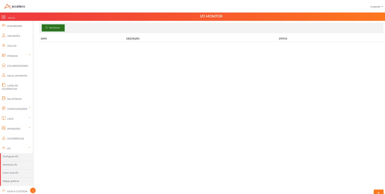
The I/O monitoring screen allows viewing, in real time, the status of configured variables.
Navigation path: I/O > Monitor I/O
How It Works
- Go to the monitoring screen
- Click the Monitor button to start real-time monitoring
- All variables that have a Monitor type action configured will be presented with their respective values
- The values are updated automatically whenever there is a change
Only variables that have a "Monitor" action configured in some handler will appear on this screen. To add a variable to monitoring, configure a "Monitor" action in the corresponding handler.
Conditioning of Variable Values
In some situations, it is necessary to perform a pre-processing of a variable's values as soon as they are updated.
Navigation path: I/O > I/O signal cond.
Concept
Conditioning allows "parsing" raw values into more meaningful values before the values are delivered to the handlers, simplifying configuration and operation.
Configuration
To create a signal conditioner:
- Navigate to
I/O > I/O signal cond. - Click New conditioner
- Select the variable to be conditioned (controller inputs, virtual variables, etc.)
- Define the conditioning rules
Conditioning Rules
The rules are handled sequentially, ordered in ascending order by the Order field:
- The first rule that is considered TRUE will be applied, conditioning the signal to the configured value
- If no rule is true, no conditioning will be applied and the original value of the variable will be used in the handlers
Practical Example
Scenario: A device emits an analog signal from 0 to 100. We want to classify the values into LOW/MID/HIGH levels.
Conditioner configuration:
| Order | If value is | Rule | Condition to |
|---|---|---|---|
| 1 | ≤ | 20 | LOW |
| 2 | ≤ | 80 | MID |
| 3 | > | 81 | HIGH |
Result: In the I/O handlers, the rules can check the values using LOW, MID, and HIGH (textually) instead of the raw analog values, simplifying the configuration.
Without conditioning:
  Rule: SENSOR_TEMP >= 81 → Trigger ventilation

With conditioning:
  Conditioner: SENSOR_TEMP → LOW/MID/HIGH
  Rule: SENSOR_TEMP = HIGH → Trigger ventilation
Conditioning is especially useful when working with analog sensors that emit continuous numeric values and you want to simplify the handler rules using textual categories.
Practical Examples
Example 1: Open Door Alarm
Objective: Trigger a siren if the door sensor stays active for more than 30 seconds.
Handler: MAIN DOOR ALARM
General data:
  Rule application: AND
  Symmetric actions: YES

Triggers:
  - INPUT01 of the GATE I/O MODULE

Rule:
  INPUT01 of the GATE I/O MODULE = 1 (ON) for 30 SECONDS

Actions:
  1. Act on output: OUTPUT03 (Siren) = ON
  2. Generate popup: "Main door open for more than 30s" for all operators
  3. Generate incident

Since symmetric actions = YES:
  → When the rule is true: turns on the siren, generates a popup and an incident
  → When the rule becomes false again: turns off the siren automatically
Example 2: Sensor Consolidation with Macro
Objective: Calculate the average of 3 temperature sensors and alert if it exceeds the limit.
Handler 1: CALCULATE AVERAGE
Triggers:
  - TEMP_SENSOR_1, TEMP_SENSOR_2, TEMP_SENSOR_3

Rule:
  TEMP_SENSOR_1 > 0 for 0 SECONDS (always true when there is a reading)

Actions:
  1. Execute macro: MEDIA_TEMP = AVERAGE(TEMP_SENSOR_1,TEMP_SENSOR_2,TEMP_SENSOR_3)
  2. Monitor: MEDIA_TEMP (presentation: Text)

---

Handler 2: TEMPERATURE ALERT
Triggers:
  - MEDIA_TEMP

Rule:
  MEDIA_TEMP > 40 for 60 SECONDS

Actions:
  1. Act on output: OUTPUT01 (Ventilation) = ON
  2. Generate popup: "Average temperature above 40°C" for operators
Example 3: Panic Button
Objective: Automatic response to a panic button press.
Handler: PANIC BUTTON
Triggers:
  - INPUT02 of the RECEPTION I/O MODULE (panic button)

Rule:
  INPUT02 of the RECEPTION I/O MODULE = 1 for 0 SECONDS

Actions:
  1. Act on output: OUTPUT01 (Siren) = ON
  2. Play Barium sound: Device 1, Track 3
  3. Generate popup: "PANIC: Button pressed at reception" for all operators
  4. Generate incident
Best Practices
-
Name clearly: Use descriptive names for handlers, variables, and actions
-
Avoid loops: Be careful with actions that trigger handlers in a cycle (handler A changes a variable that is a trigger for handler B, which changes a variable that triggers A)
-
Use symmetric actions: When possible, configure symmetric actions to avoid creating duplicate handlers to turn on/off
-
Take advantage of conditioning: For analog sensors, use signal conditioning to simplify rules
-
Use chaining: Break complex logic into multiple handlers using intermediate variables
-
Monitor key variables: Configure a "Monitor" action for important variables for visual tracking
-
Test with the simulator: Use the Simulator to validate behavior before activating in production
-
Configure persistence time: Use appropriate times in the rules to avoid triggering by momentary variations
Next Steps
- Controllers - Configure I/O controllers
- Incident Panel - Manage incidents generated by handlers
- Synapsis - Integrate with the Synapsis module
- Logs and Monitoring - Track system events